3
2-2. Rear Panel
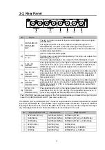
No
Name
Description
(1)
HD/SD-SDI IN
HD/SD-SDI
OUT
The left connector is used to input a serial digital component signal
(HD/SD-SDI).
The right connector is used to output an active-through out of
HD/SD-SDI IN. The jitter in the active-through output depends on
how much jitter is included in the input video. This card module has
no jitter-reducing function.
(2) SD-SDI OUT
(1 / 2)
Used to output SD-SDI signals.
Signals, down-converted and adjusted by Proc Amp, are output if an
HD-SDI signal is input.
Proc Amp adjusted signals are output if an SD-SDI signal is input.
(3)
Y / G / C1
(HD/SD,
ANALOG OUT)
The signal input from (1) or the signal output from (2) is D/A converted
and output from (3), (4), (5), and (6). The Y (HD/SD component), G
(RGB component) or composite signal can be output from this
connector (3).
(4)
P
B
/ B / C2
(HD/SD,
ANALOG OUT)
The signal input from (1) or the signal output from (2) is D/A converted
and output from (3), (4), (5), and (6). The P
B
(HD/SD component), B
(RGB component), Y(Y/C) or composite signal can be output from
this connector (4).
(5)
P
R
/ R / C3
(HD/SD,
ANALOG OUT)
The signal input from (1) or the signal output from (2) is D/A converted
and output from (3), (4), (5), and (6). The P
R
(HD/SD component), R
(RGB component), C (Y/C) or composite signal can be output from
this connector (5).
(6)
SYNC / C4
(HD/SD,
ANALOG OUT)
The signal input from (1) or the signal output from (2) is D/A converted
and output from (3), (4), (5), and (6). The composite, bi-level sync, or
tri-level sync signal can be output from this connector (6).
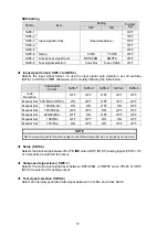
The FUNCTION (see previous page) on the front panel enables you to select the type of signal
output from HD/SD ANALOG OUT (see also section 4-3).
The SD-SDI OUT and ANALOG OUT connector output a down-converted signal and/or a signal
input from HD/SD-SDI IN. The available output signal formats of these two outputs for different
input signal formats are as shown in the table below. The unit may not output signals correctly if
any other signal format than those listed below is used to input to the unit.
No
Input Signal Format
SD-SDI OUT
ANALOG OUT
①
525/59.94
(NTSC)
525/59.94
(NTSC) 525/59.94 (NTSC)
②
1080/59.94i
525/59.94
(NTSC) 525/59.94 (NTSC) or 1080/59.94i
③
720/59.94p
525/59.94
(NTSC) 525/59.94 (NTSC) or 720/59.94p
④
625/50 (PAL)
625/50 (PAL)
625/50 (PAL)
⑤
1080/50i
625/50 (PAL)
625/50 (PAL) or 1080/50i
⑥
720/50p
625/50 (PAL)
625/50 (PAL) or 720/50p
2
1
SYNC/C4
P /R/C3
P /B/C2
Y/G/C1
Y
B
R
C
SD-SDI OUT
HD/SD-SDI IN
HD/SD ANALOG OUT
UFH-70DCM
(1)
(2)
(3)
(4)
(5)
(6)
Summary of Contents for UFH-70DCM
Page 1: ...UFH 70DCM HD SD Down Converter with D A Converter 1st Edition Rev 1 OPERATION MANUAL...
Page 2: ......
Page 6: ......
Page 22: ......

