background image

71 


No. 

Item 

Description 

(2) 

DF/NDF display 

Differentiation between drop frame mode and non-drop frame mode (*1) 
de pends on the input signal when the setting calls for the ancillary TC to 
be embedded. In the case of a fixed TC, the display depends on the 
setting in the 

Timecode (Rec)

 screen. 

(3) 

Time code 
display 

When the 

LTC source

 in the Input Signal Settings screen is set to 

SDI ancillary

, "

ATC

" is displayed if SDI input signal is present. 

When the 

LTC source

 in the Input Signal Settings screen is set to 

LTC IN

, "

LTC

" is displayed if LTC input signal is present. In either 

case, no characters are displayed, if SDI or LTC input is not present,   

(4)


IN point TC 

(*2)


Displays the time code at which recording starts. The setting is changed 
in the 

Timecode (Rec) 

screen.  

(5)


OUT point TC 

(*2)


Displays the time code at which recording stops. The setting is changed 
in the 

Timecode (Rec)

 screen.  

(6)


DURATION 

Displays the recording duration. The setting is changed in the 

Timecode (Rec)

 screen.   

*1  DF or NDF is displayed at 59.94i or 59.94p 

*2  The time code fields should be left blank if recording in Manual mode. 


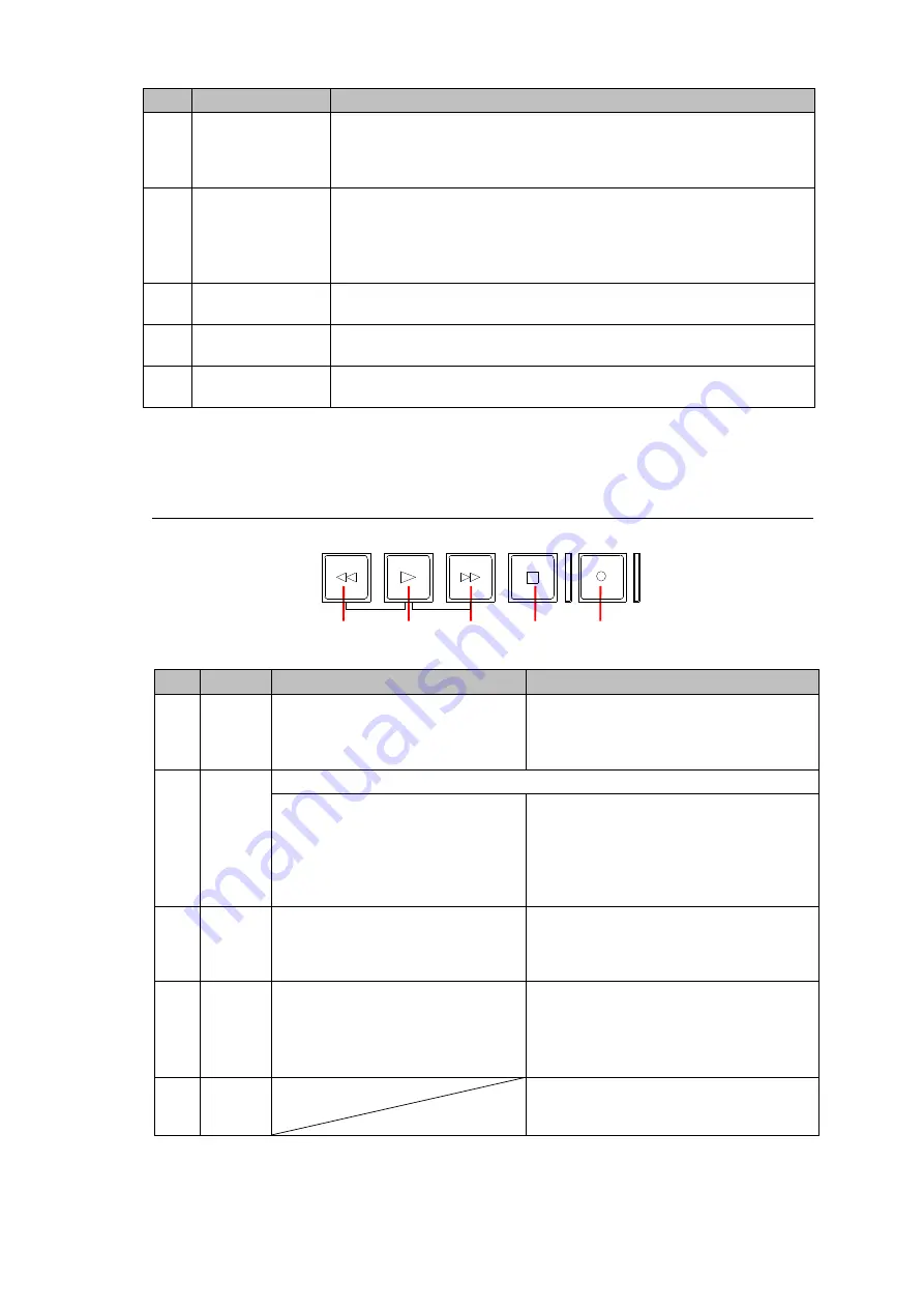
5-1-4. Recording and Playback Control Area 


No. 

Button 

In Playback mode 

In Recording mode 

(1) 

REV 

Reverses (fast rewinds) the file 
being played back. The maximum 
possible reverse speed is 4×. The 
button is lit during reversing. 

In the case of the “REM.1” setting, 
instructs the VTR connected using 
RS-422 to reverse. 

(2) 

PLAY 

Instructs execution based on the item with [

PLAY

] in the menu screen. 

Plays back the open MXF file at 
normal speed. During playback, 
the button is lit. 

Pressing [

PLAY

] while holding down 

[

REC

] starts recording. While recording, 

the button is lit. 
In the case of the “

REM.1

” setting, 

instructs the VTR connected using 
RS-422 to reverse. 

(3) 

FWD 

Fast forwards the file being played 
back. The maximum possible fast 
forward speed is 4×. While fast 
forwarding, the button is lit. 

In the case o

f the “

REM.1

” setting, 

instructs the VTR connected using 
RS-422 to fast forward. 

(4) 

STOP 

Temporarily stops playback. While 
playback is stopped, the button is 
lit. 

Stops recording. While recording is 
stopped, the button is lit. 
In the case of the “

REM.1

” setting, 

instructs the VTR connected using 
RS-422 to stop. 

(5) 

REC 


Pressing [

PLAY

] while holding down 

[

REC

] starts recording. While recording, 

the button is lit. 


(1) 

(2) 

(3) 

(4) 

(5) 

REC

STOP

FWD

PLAY

REV

Summary of Contents for LTR-200HS7

Page 1: ...LTR 200HS7 LTO 7 Video Archiving Recorder 1st Edition OPERATION MANUAL...

Page 2: ...2 Edition Revision History Edition Revision Date Description Section Page 1 2016 12 16 First edition...

Page 3: ...ound the unit to gas lines units or fixtures of an explosive or dangerous nature Operation Hazard Do not operate the unit under hazardous or potentially explosive atmospheric conditions Doing so could...

Page 4: ...d disconnect the power cord to avoid potentially hazardous conditions If problems similar to the above occur contact an authorized service representative before attempting to operate the unit again Ra...

Page 5: ...gn materials Do not keep them in LTO drive s Doing so will result in errors 7 Before powering ON the LTO unit ensure that no condensation has formed on the unit which may result in malfunction Do not...

Page 6: ...Denker Jean Michel Dubois Jean loup Gailly Hunter Goatley Ed Gordon Ian Gorman Choursis Herborth Dirk Haase Greg Hartwig Robert Heath Jonathan Hudson Paul Kienitz David Kirschbaum Johnny Lee Onno van...

Page 7: ...Copyright c 2007 Eli Fant elifantu mail ru Copyright c 2009 Daniel Stenberg Copyright C 2008 2009 Simon Josefsson All rights reserved Intel R JPEG Library 1 5 Copyright C 1998 2000 Intel Corporation...

Page 8: ...luded LTO cleaning cartridge 1 CD ROM 1 LTR 200HS7 Operation Manual PDF LTR NAS Operation Manual PDF LTR PD SD Operation Manual PDF LTR PRS Operation Manual PDF LTO Series Usage Notes PDF Tutorial 1 U...

Page 9: ...Settings Screen 31 4 4 Timecode Display and Setting Screen Recording 32 4 5 Timecode Display and Setting Screen Playback 32 4 6 Metadata Display and Setting Screen 33 4 7 Setting Screens 35 4 7 1 Reco...

Page 10: ...85 7 4 Supported LTO Tape 86 8 Specifications and Dimensions 87 8 1 Specifications 87 8 2 Proxy Video 89 8 2 1 H 264 File 89 8 2 2 Windows Media File 89 8 3 LTO 5 Basic Performance 90 8 4 LTO 6 Basic...

Page 11: ...Furthermore using an IBM LTFS file system the files recorded by this archiving system on LTO tapes can be read by other systems and the LTO tapes can be used as media for material or program changes...

Page 12: ...keyboard Used to input characters in the Metadata screen etc For details refer to 2 4 3 Formatting an LTO Tape Cartridge and 4 6 Metadata Display and Setting Screen USB bar code reader keyboard type...

Page 13: ...tails refer to 4 1 Main Menu Screen The META TC and LTO shortcut buttons display the Metadata screen Timecode screen and LTO Operations screen respectively For details refer to 5 1 5 Menu Control Area...

Page 14: ...wait is displayed on the screen at startup About 3 minutes after the power has been turned on a screen similar to the one shown on the left will appear on the LCD monitor after which normal operation...

Page 15: ...e message shown in the figure below is displayed when the Power button on the front panel is pressed Press the Power button again to shut down the system It will take several minutes for the power to...

Page 16: ...e cartridge pointing in the direction shown in the figure horizontally 2 The LTO tape will automatically mount 1 Tape Mounting using the Menu 1 With the LTO tape cartridge pointing in the direction sh...

Page 17: ...fore they are use Eight character string LTO barcode IDs ending with an L6 or L7 and called Media IDs are printed on tape labels and used to identify LTO tapes in LTR Series devices Use a unique media...

Page 18: ...ons to open the LTO Operations menu screen 3 Select Copy LTO tape single drive 4 When the Copy LTO tape single drive message see below appears press ENTER If an LTO tape cartridge is already mounted w...

Page 19: ...le either of the following messages is displayed 2 When the following message appears press the ENTER button to cancel copying Pressing the MENU button resumes copying 7 Once file copying is finished...

Page 20: ...is going message appears press the ENTER button to cancel writing Pressing the MENU button resumes writing 10 Once writing is finished the message Writing file is done see below appears A To write to...

Page 21: ...s refer to 5 1 2 Switches 3 Set the profile of the file to be recorded For details on profiles refer to 4 7 2 Recording Settings 2 Screen 4 Press the PLAY button while holding down the REC button to s...

Page 22: ...4 Files can be played back by operating the PLAY and REV buttons jog dial and shuttle ring For details on the buttons jog dial and shuttle ring refer to 5 1 4 Recording and Playback Control Area and 5...

Page 23: ...unt LTO tape Eject LTO tape Format LTO tape Recover LTO tape Copy LTO tape single drive 4 2 File List Thumbnail File Info Meta Info File Operation Info Erase cache Delete Copy to tape Partial Retrieve...

Page 24: ...ecall the current settings from 2 Recall the current settings from 3 Recall the current settings from 4 Return to the factory default settings 4 7 5 File I O Mode 4 8 Show All Files 4 9 Maintenance Sh...

Page 25: ...TO tape will be displayed Format LTO tape Formats the LTO tape in the LTFS format to enable the tape to be used For details refer to 2 4 3 Formatting an LTO Tape Cartridge Recover LTO tape 1 Recovers...

Page 26: ...opened the last played file appears as the selected file indicated by a red square Item Description Thumbnail Displays thumbnails File Info First line File ID file name Second line Duration Third lin...

Page 27: ...ncel writing Files with blue background color have cached copies on the internal hard disk drive and the cached copies remain in the hard disk unless writing or deleting is executed These files can th...

Page 28: ...ox will appear Press ENTER to write copies to the LTO tape Or press MENU to cancel writing Partial retrieve 3 Displays the Partial Retrieve screen which allows new MXF files to be created by copying p...

Page 29: ...e the and buttons to select an item and use the and buttons Holding or pressed speeds up the change and jog dial to change values Holding down the or button displays values one after another When the...

Page 30: ...e ENTER button to cancel the conversion Pressing MENU at this time resume the conversion process 3 When the conversion has completed the converted file is stored in the internal hard disk drive To use...

Page 31: ...ressed operation returns to the File List screen Item Description Filter Item Sets the metadata item to be searched No Filter Does not search FileID Search by file ID GroupID Search by group ID Conten...

Page 32: ...start TC of the recorded file TC Format Select this to specify DF or NDF with the 59 94i or 59 94p format 1 Takes effect when Preset TC has been selected as the Timecode under the file setting For de...

Page 33: ...adata of the currently open file is displayed and can be modified A USB keyboard is required to perform these settings The Tab key is used to move from one item to the next The ENTER or PLAY button is...

Page 34: ...scriptions or related information and allows line breaks Rights Leave this field blank or enter any string up to 100 characters in length This field is intended for content rights use to include compa...

Page 35: ...When the ENTER or PLAY button is pressed operation transfers to the Audio Input Level and Channel Mapping screen Rec control mode Displays the recording mode settings Naming rule of MXF file Selects t...

Page 36: ...l size of listed files as blue back ground in the file list highlighted in blue in the file list YES 1copy Writes content to a cache file on the internal hard disk and to an LTO tape during recording...

Page 37: ...e maximum setting is 20 dB and the minimum setting is 60 dB 2 Channel mapping can be changed separately for channels 1 to 8 using the jog dial 3 Sound from the left or right channel to be monitored as...

Page 38: ...xHD 185 Mbps 8bit 4 2 2 Audio 24bit 8ch 1920x1080 50i MXF DNxHD 185 Mbps 10bit 4 2 2 Audio 24bit 8ch 1920x1080 50i MXF DNxHD 115 Mbps 8bit 4 2 2 Audio 24bit 8ch 1280x720 50p MXF DNxHD 175 Mbps 8bit 4...

Page 39: ...ettings ENTER will be grayed out and cannot be set when Proxy output is set to No Output Proxy Settings Use the and buttons to select an item and the ENTER or PLAY button to enter select settings or t...

Page 40: ...the setting using the jog dial Item Description Audio level mapping Play When the ENTER or PLAY button is pressed operation transfers to the Audio Output Level and Channel Mapping screen Audio referen...

Page 41: ...not superimposed or output Back color Specifies the background color for the time code which is superimposed and output to SDI OUT3 and 4 on the rear panel Black Black background White White backgroun...

Page 42: ...1 Sound from the left or right channel to be monitored as the sound heard thorough the headphones or internal speakers can be selected using the jog dial 2 The audio level can be separately adjusted...

Page 43: ...1 37 04 ns 0 625 50 864 863 32 00 s to 31 96 s 1 37 04 ns 0 V Phase TV system Adjustment range Step Initial value 1080 59 94i 562 lines to 562 lines 16 68 ms to 16 68 ms 1 line 29 66 s 0 1080 50i 562...

Page 44: ...SDI input signals are present AES AES IN 1 2 AES IN 3 4 or AES IN 1 2 3 4 is displayed depending on the AES input signals LTC Indicates whether LTC input signals are present Video format Indicates th...

Page 45: ...Y 3 A confirmation dialog box will appear 4 Press ENTER The settings will be applied and the system will automatically reboot To Return to Default 1 Use and to align the cursor with Return to the fact...

Page 46: ...bling files on the LTO tape to be directly read from or written to the PC Press the ENTER PLAY or MENU button to restore the Monitoring screen Operation cannot be changed to File I O mode while record...

Page 47: ...tting for the number of simultaneous transfers has been established Check on the Force UTF 8 box if you want to name files or directories using any characters in multi byte characters such as Japanese...

Page 48: ...the destination For details refer to the table below User name Password Destination Function fileio ltrltr21 LTO tape Reads writes files on the LTO cartridge metadata 3 ltrltr21 Metadata Set from ext...

Page 49: ...nd buttons or the jog dial to select an item and use the ENTER or PLAY button to enter settings When the MENU button is pressed operation returns to the Main Menu screen Item Description Shutdown Shut...

Page 50: ...Item Description Auto mount LTO tape Sets whether to automatically mount LTO tapes that are inserted ON LTO tapes are automatically mounted OFF LTO tapes must be mounted manually See section 2 4 1 Ins...

Page 51: ...n UTC time Media Efficiency Overall LTO tape condition 0 Unknown 1 Optimal condition 255 Worst condition Loading Count Total number of LTO tape cartridge to LTO drive mount times Top Passes Total numb...

Page 52: ...e cases the file size may exceed 10 MB 4 10 2 Saving the System Log The procedure for saving the system log is described below When a malfunction has occurred and a FOR A support staff member requests...

Page 53: ...ils refer to GPI Settings in the following pages Change date time Sets the LTR recorder date and time For details refer to Change Date Time in the following pages Firmware update Updates the internal...

Page 54: ...utton and shut down the system Item Description Host name 2 Used to enter a host name Obtain an IP address automatically Enable Obtains an IP address automatically Disable Sets IP address and other ne...

Page 55: ...Stop File I O Stops file input output IN 2 Sets the GPI IN 2 functions Selection options are the same as for GPI IN 1 For details on available options refer to GPI IN 1 IN 3 Sets the GPI IN 3 functio...

Page 56: ...ually Time Sets the time manually Time Zone 1 Sets the time zone SNTP Enables disables the auto time setting using SNTP Simple Network Time Protocol Enable Enables the auto time setting The time setti...

Page 57: ...m screen is restored When fileio or metadata is selected the following screen appears respectively After inputting the information in the fields 1 use the ENTER button to apply the settings When the M...

Page 58: ...MODE See 5 1 2 Switches Preroll times from 1 to 10 seconds can be set Network Output Settings Specifies a network storage location for output recording files When Network output settings is selected i...

Page 59: ...the ENTER button When the MENU button is pressed the Network Output Settings screen is restored 1 A USB keyboard is required to enter the settings The message Caps Lock ON or Num Lock ON appears to r...

Page 60: ...to Group IDs then File IDs Auto LTO index data reading Selects whether to load a tape index when mounting an LTO tape YES A tape index is read After mounting a tape thumbnails and metadata are also di...

Page 61: ...an allows your device to be remotely monitored and receive updates via the Internet from FOR A To subscribe to the Remote Support plan provide your ID and Password under Account information as shown b...

Page 62: ...MENU button to return to the Monitoring screen Operation cannot be changed to Remote Mode while recording is in progress If there is any file open for playback the file closes and the mode shifts to...

Page 63: ...ule in the schedule list then press the TC button to display the Scheduled Recording Setting screen in which the selected schedule can be edited After changes are complete press Modify then ENTER to u...

Page 64: ...ing mode or changing format in Encoder Profile saving delays may occur in successively input recordings and may require up to several minutes about once every 17 times If a period between entries in t...

Page 65: ...its content 3 Open the Main Menu screen on the LTR recorder and select OP Atom Ingest 4 An MXF OP Atom file list will be displayed Select a file from the list and press ENTER 5 The Metadata screen wi...

Page 66: ...uring recording or playback can be monitored using a headphone or internal speaker The control knob is used to adjust the volume level Note that when a headphone is plugged in the internal speaker is...

Page 67: ...an be changed on these screens 3 REMOTE REM 1 Images are recorded on the VTR while the VTR is automatically controlled REM 2 Images are recorded when the awaited time code is received REM 3 This item...

Page 68: ...ted in green levels of 13 6 dB up to 6 5 dB are indicated in yellow and levels above 6 5 dB are indicated in red 3 Playback position display A green horizontal progress bar appears in the upper row re...

Page 69: ...ode Displays the TOP and END point TCs and DURATION This displays the IN and OUT point TCs and DURATION For details refer to 5 1 3 2 Start and End Timecode Display 5 1 3 1 Decoding Encoding Status No...

Page 70: ...n Playback mode No Item Description 1 TOP point TC Displays the start time code of the MXF file now open 2 END point TC Displays the end time code of the MXF file now open 3 DURATION Displays the play...

Page 71: ...t blank if recording in Manual mode 5 1 4 Recording and Playback Control Area No Button In Playback mode In Recording mode 1 REV Reverses fast rewinds the file being played back The maximum possible r...

Page 72: ...oint 4 SET OUT Used to move between screens Playback jumps ahead by the time equivalent to the interval specified by Jump Distance in the Timecode Play screen The time code at the point when the butto...

Page 73: ...o perform jog operations 4 Shuttle ring 2 Used to play the MXF file being played back at a variable speed When rotated clockwise the file is played in the forward direction when rotated counterclockwi...

Page 74: ...t metadata LAN1 is connected to the PC via a switching hub Do not use LAN2 which is for maintenance use only 9 USB connector The USB keyboard or USB bar code reader is connected here 10 GPI ALARM Alar...

Page 75: ...I IN HD SDI signals are input here The system operates in Input Lock mode when recording 2 SDI OUT 1 HD SDI signals are output from here The same images and sound are output to SDI OUT1 SDI OUT2 SDI O...

Page 76: ...ignal ground 5 NC No connection 6 SG Signal ground 7 Tx Out Transmit Data 8 Rx In Receive Data 9 FG Frame ground Wiring Diagram for RS 422 Connection Cable LTR side VTR side 9 pin D sub female 9 pin D...

Page 77: ...NC Not connected 11 NC Not connected 12 GPI OUT3 Out GPI output 4 13 GPI OUT2 Out GPI output 4 14 GPI OUT1 Out GPI output 4 15 GND Ground 0V 1 Refer to Alarm output circuit below 2 Refer to GPI input...

Page 78: ...ensure safety and stable operation a grounded outlet must be used or the LTR recorder must be grounded using the ground terminal 2 Ground terminal Shorted with ON LTR 200HS7 side GPI IN GPI IN1 3 GND...

Page 79: ...nce screen LTO driver maintenance LTO Driver Maintenance 3 Execute Repair slow mounting LTO tape 4 If the problem cannot be remedied contact the FOR A Service Center 3 The cartridge cannot be mounted...

Page 80: ...r at the bottom left of the screen If SDI is blinking a mistake may have been made in the SD HD image settings If HD has been selected as the Encode Profile setting in the Setting screen change to SD...

Page 81: ...Select setting to input LTC output signals from the VTR to the LTR recorder and to use LTC signals For details on the setting method refer to 4 7 4 Input Signal Settings Screen 11 When recording at th...

Page 82: ...ton is pressed In such case such case check that the bottom LED of the two LEDs under the front panel Power button is not blinking and unplug the power cord on the rear panel If the problem is not rem...

Page 83: ...ng recording the recording process may stop in some cases The Monitoring screen built in speaker and headphone out are provided only for monitoring use and to ensure easy operation To precisely check...

Page 84: ...ixed use IN DUR mode 4 4 5 1 2 When VITC and LTC timecodes are both embedded in SDI signals the VITC timecode will be displayed on the SDI OUT3 and 4 output video even if the LTC source is set to SDI...

Page 85: ...ject and immediately reinsert into the drive during writing retries In such case the process may take several minutes Or playback may continue until the end of the cached data and stop due to the cach...

Page 86: ...sure to keep the file size smaller than 1 MB When recording with some codecs the timecode data is incremented continuously from the start timecode Therefore discontinuous timecode may not be recorded...

Page 87: ...bit 4 2 2 Audio 24 bit 8ch DNxHD 145 8 bit 4 2 2 Audio 24 bit 8ch DNxHD 175 8 bit 4 2 2 Audio 24 bit 8ch DNxHD 185 8 bit 4 2 2 Audio 24 bit 8ch DNxHD 220 8 bit 4 2 2 Audio 24 bit 8ch DNxHD 175 10 bit...

Page 88: ...ot used GPI ALARM 15 pin D sub female x 1 ALARM Power Fan alarm relay contact GPI 3 input 3 output contact input open collector output MAINTENANCE 15 pin mini D sub female VGA x 1 maintenance only Tem...

Page 89: ...ch frame as the Picture Timing SEI message in H 264 streams Supports discontinuous timecodes Timecode can be added to the video itself by changing setting 8 2 2 Windows Media File Video Standard Windo...

Page 90: ...lues excluding ancillary data and proxy video files are theoretical Actual values may differ depending on LTO tape and head conditions MPEG 2 422 HL Approx 80 hours 50Mbps HD AVC Intra 100 HD Approx 4...

Page 91: ...L LTO RECORDER LTR 200HS USB AUDIO METER PLAY LEVEL REM 1 IN OUT REC LOCK IN DUR MANUAL REM 3 2 501 5 32 15 420 533 5 41 5 72 212 130 8 10 2 22 4 30 152 30 26 1 2 3 4 MAINTENANCE GPI ALARM LAN1 LAN2 U...

Page 92: ...n the equipment is operated in a commercial environment This equipment generates uses and can radiate radio frequency energy and if not installed and used in accordance with the instruction manual may...

Page 93: ...of Canada 1131A Leslie Street Suite 209 Toronto Ontario M3C 2J6 Canada Tel 1 416 977 0343 Fax 1 416 977 0657 FOR A Europe S r l Via Volturno 37 20861 Brugherio MB Italy Tel 39 039 91 64 811 Fax 39 03...

Reviews: