FOR-A HVS-390HS Operation Manual Download Page 191

191 

FS ENABLE 

Enables/disables FS for each input. 

ON: Lit orange 

OFF: Unlit 

EVENT NO0-9 RECALL 

Loads an event. 

Event stored: Lit 

Event not stored: Unlit 

AUX1-8 TRANS ENABLE 

Sets AUX Crossfade transitions to On 

or Off. 

ON: Lit orange 

OFF: Unlit 

VIRTUAL ENABLE 

Enables Virtual Link. 

ON: Lit orange 

OFF: Unlit 

ROUTER ENABLE 

Enables router control. 

AUX LINK ENABLE 

Enables AUX LINK. 

MACRO BUS SELECT 

Sets the KEY/AUX bus to Macro 

mode. 


22-3. Triggering User Buttons 

User buttons can be triggered (activated) by state changes (ON/OFF) of tally or GPI function 
items. This chapter shows how to set settings for these examples in the USER BUTTON menu. 
Three typical examples are shown below: 
 
Ex. 1:  

Starts KEY1 SCALER transitions 

when

 IN01 is displayed on the M/E2 PGM 

screen. 

Ex. 2:  

Starts KEY2 MIX transitions

 when

 IN01 is cleared from the M/E2 PGM 

screen. 

Ex. 3:  

Plays video on VTR1

 when 

KEY1 is ON


<Ex. 1> 

To execute the Ex. 1 procedure using USER Button 1, set the menu as shown below.  
 
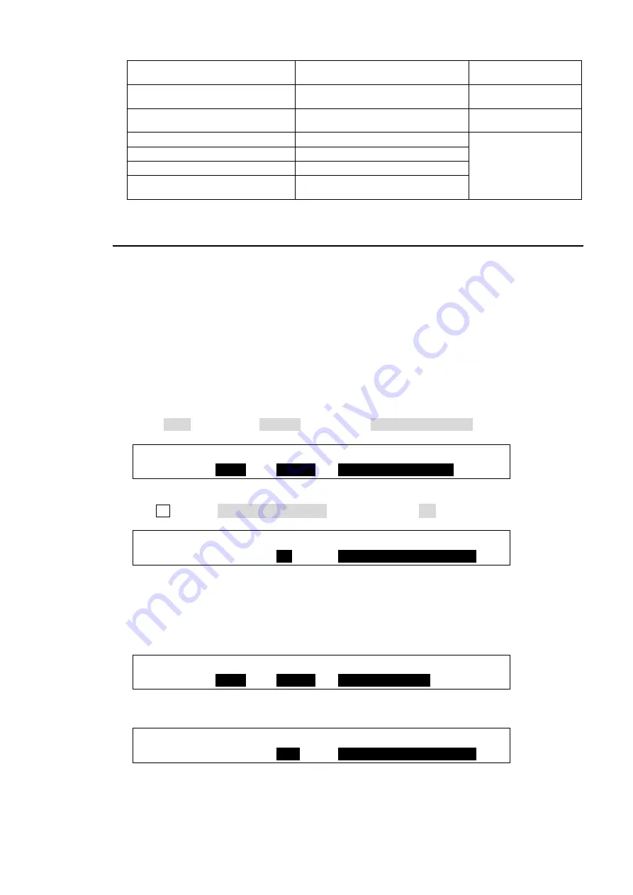
(1) Open PAGE 1 of the [USER BUTTON] menu. 
(2) Select OU-1 for SELECT, USTRS for TYPE and ME1 KEY1 SCALER in the next field. 
 

USER   :SELECT : TYPE  : FUNC(F3)      : 1/2  
BUTTON : =

OU-1

 : =

USTRS

: =

ME1 KEY1 SCALER


(3) Press the page down button to go to PAGE 2. 
(4) Turn F3 to select Out:RED TALLY-IN01. Set TRG EDG to ON. 
 

USER   :SELECT :TRG EDG: FUNCTION(F3)  : 2/2  
BUTTON : =OU-1 : =

ON

   : =

Out:RED TALLY-IN01


<Ex. 2> 

To execute the Ex. 2 procedure using USER Button 2, set the menu as shown below.  
 
(1) Set PAGE 1 of the [USER BUTTON] menu as shown below. 
 

USER   :SELECT : TYPE  : FUNC(F3)      : 1/2  
BUTTON : =

OU-2

 : =

USTRS

: =

ME2 KEY2 MIX


(2) Set PAGE 2 as shown below. (See the table on the next page for details on TRG EDG.) 
 

USER   :SELECT :TRG EDG: FUNCTION(F3)  : 2/2  
BUTTON : =OU-2 : =

OFF

  : =

Out:RED TALLY-IN01


Summary of Contents for HVS-390HS

Page 1: ...HVS 390HS Digital Video Switcher HVS 392OU HVS 392ROU HVS 392WOU Operation Unit 3rd Edition Rev 7 OPERATION MANUAL...

Page 2: ...he router simultaneous switching description Corrected FTP connection description Contorable Menus via Brower added Sec 12 4 p5 15 227 241 Sec 26 2 6 Sec 30 3 Appendix 3 3 2013 06 28 Added HVS 392WOU...

Page 3: ...ound the unit to gas lines units or fixtures of an explosive or dangerous nature Operation Hazard Do not operate the unit under hazardous or potentially explosive atmospheric conditions Doing so could...

Page 4: ...d disconnect the power cord to avoid potentially hazardous conditions If problems similar to the above occur contact an authorized service representative before attempting to operate the unit again Ra...

Page 5: ...Output Expansion Card Max 2 cards HVS 30TALR 1 2 Tally Output Expansion Card Relay type Max 2 cards 37 pin D sub connector 1 set for cable fabrication HVS 39EXTME 1 M E Expansion Card for upgrading f...

Page 6: ...designed for rack mount use HVS 392WOU A full featured 2 M E 28 button control panel Other Options ITEM QTY REMARKS HVS 30RU 1 2 Remote Control Unit HVS AUX8 HVS AUX16 HVS AUX32 1 5 AUX bus Control u...

Page 7: ...oughly to ensure you understand the product Afterwards it is important to keep this manual in a safe place and available for future reference Font Conventions The following conventions are used throug...

Page 8: ...4 1 2 Other Menu Access Buttons 36 4 1 3 USER Button Menu Shortcut 36 4 2 How to Set Values 37 4 2 1 Displaying Parameters 37 4 2 2 Changing Settings or Values Using F1 to F4 38 4 2 3 Changing Settin...

Page 9: ...Groups 64 6 8 3 Enabling AUX LINK 64 7 Bus Operation 66 7 1 Selecting Video Sources 66 7 1 1 Selecting Video Sources on M E1 and M E2 67 7 1 2 Selecting Video Sources for AUX Outputs 68 7 2 Button Sw...

Page 10: ...KEY INSERT AUX 100 10 5 Adjusting the Key Signal 101 10 6 Chroma Key 102 10 6 1 Creating a Chroma Key 102 10 6 2 Chroma Key adjustments 103 10 6 3 Advanced Example 1 Using KEY INSERT AUX 105 10 6 4 Ad...

Page 11: ...13 3 Clearing Clip Data 127 14 CG WIPE 128 14 1 CG WIPE Operation Example 1 129 14 2 CG WIPE Operation Example 2 130 14 3 Saving CG WIPE Settings 132 14 4 CG WIPE Menu Quick Reference 132 15 Multivie...

Page 12: ...162 18 4 Operation Example 2 163 18 5 Macro Memory Operation 164 18 5 1 Overwrite Protection 164 18 5 2 Naming Macros 164 18 5 3 Deleting Macros 165 18 6 Macro Execution Buttons 166 18 6 1 Assigning...

Page 13: ...194 24 1 1 GPI IN 194 24 1 2 GPI OUT 195 24 1 3 OU GPI O 195 24 2 Tally Output 200 24 2 1 Tally Color Settings 200 24 2 2 Tally Output Settings GPI TALLY OUT 200 24 2 3 Tally Output Settings HVS 30TA...

Page 14: ...Setting 221 29 Editor Control Option 223 29 1 Editor Control Settings 223 29 2 Connection Settings with Editor EDITOR port setting 224 30 AUX Bus Control Units 225 30 1 HVS AUX8 16 32 225 30 1 1 Conn...

Page 15: ...l Panels 248 35 3 2 5 M E Mode 249 35 3 1 P P Setup 250 35 3 2 P P Control 250 36 Setup Setting for HVS 30RU 252 36 1 Assigning Sources to PGM PST Bus buttons 252 36 2 Setting USER Buttons 253 37 Spec...

Page 16: ......

Page 17: ...k mount use HVS 392WOU 2 M E 28 button Control Panel Two control panels HVS 30OU RU for HVS 300HS are also available HD SD SDI 16 input 8 output and an HDMI output Max 24 input 13 output Variety of I...

Page 18: ...This indicator works the same as the ALARM indicator located on the Control panel 2 Power switch 2 For Power 2 ON OFF option POWER 2 indicator Lit green Power is supplied to the unit Unlit Power is no...

Page 19: ...female Used to connect external devices such as Hanabi tally units HVS 30RU VTR VDCP devices routers and audio mixers 2 4 2 10 TO OU Used for control panel HVS 391OU and HVS 392OU ROU WOU connection...

Page 20: ...EDIT COPY SWAP USERBUTTON MENU SEQUENCE EVENT MACRO W IPE US ERB UTTO N KE Y A UX USB M EMORY b t s c d k c c BLACK TRANS SEQUENCE EVENT WIPE MENU USER BUTTON MEM ORY CONTROL MACRO SEQ EDOT COPY SWAP...

Page 21: ...unctions can be assigned to these buttons 22 7 BUS SELECT Block Used to select a bus then to select a video in the KEY AUX bus No 8 6 2 1 t s n b t s BLACK TRANS SEQ UEN C E EVEN T MAC R O M E M ORY C...

Page 22: ...ed for service purposes Do not use 2 TO MU Arcnet port Used for the main unit connection The other connector loopthrough can be used for AUX unit connection The loopthrough connector must be 75 ohm te...

Page 23: ...t per card Refer to sec A IN 1 B IN 2 HVS 30HSDI A HD SD SDI BNC w o resize function 4 inputs 5 10 HVS 30HSDI HD SD SDI BNC w resize function 4 inputs HVS 30HSAI HD SD analog component or Analog compo...

Page 24: ...escription 1 FG Frame ground 2 R In Receive data 3 T Out Transmit data 4 SG Signal ground 5 NC Not used 6 SG Signal ground 7 R In Receive data 8 T Out Transmit data 9 FG Frame ground RS 422 ports are...

Page 25: ...UTO TRANS default setting 8 M E2 KEY2 AUTO TRANS default setting 9 M E2 KEY3 AUTO TRANS default setting 10 M E2 KEY4 AUTO TRANS default setting 11 Not used 12 Not used 13 Signal ground 14 Signal groun...

Page 26: ...D TALLY IN13 default setting 14 RED TALLY IN14 default setting 15 RED TALLY IN15 default setting 16 RED TALLY IN16 default setting 17 RED TALLY IN17 default setting 18 RED TALLY IN18 default setting 1...

Page 27: ...ound 8 Signal ground 9 OUT M E1 BKGD TRANS STS default setting 10 OUT M E1 KEY1 TRANS STS default setting 11 OUT M E1 KEY2 TRANS STS default setting 12 OUT M E1 KEY3 KEY2 TRANS STS default setting 13...

Page 28: ...rmally Open 9 36 TALLY OUT18 Normally Open 18 18 TALLY OUT9 COMMON 37 TALLY OUT18 COMMON 19 Reserved Normally Open Open when a tally is present and closed with COMMON pin when no tally is present Do n...

Page 29: ...ch output is 400 mA The HVS 30TALR is a relay board Use the supplied or commercially prepared 37 pin D sub male connector with 4 40 inch screws for making a connection cable HVS 30TALR side TALLY OUT...

Page 30: ...M TSG Reference VIDEO SERVER VCR etc 75 termination Reference HD SD SDI 75 termination Reference RATING LABEL CONTROL TOM U G PI TA LLYOUT S ERV ICE AC100 240V50 6 0HzIN POWER1 PO W ER ON OFF POWER2 A...

Page 31: ...GPI IN SDI OUTPUT 1 2 A B 1 2 1 2 3 4 5 6 7 8 SDI INPUT 9 10 11 12 13 14 16 15 GPI TALLY OUT OPTION SLOT C D 1 AC100 240V50 60HzIN RATING LABEL TO OU GENLOCK REFIN REFOUT LAN 1 2 3 4 5 6 3 4 5 6 To I...

Page 32: ...etup is very easy Just connect the MU and OU Any additional network setting is not necessary However if your HVS 390 series system has two or three OU units the Arcnet ID of devices should be changed...

Page 33: ...f the power of the MU and OU units 8 Connect all devices in the system and power them on NOTE If connecting multiple control and remote panels to the system refer to section 35 Connecting Control and...

Page 34: ...ect ratio SYSTEM FORMAT ASPECT SW TMNG 1 1 FORMAT 1080 59 94i 16 9 ANY 6 Press the page up button to return to the SETUP SYSTEM menu 7 Turn F1 to select REBOOT and press F1 Press ENTER in the SELECT K...

Page 35: ...pad change the Keypad mode Mode Selection Buttons Button Function MENU Changes the Keypad to menu access buttons Pressing on a button in the Keypad displays the related menu The MENU control button bl...

Page 36: ...TRANS 1 6 menu WIPE Pressing twice quickly WIPE PATTERN menu FADER LIMIT Pressing once TRANS LIMIT menu TRANSITION RATE Pressing once TRANS 1 6 menu PATTERN Pressing once WIPE PATTERN menu 4 1 3 USER...

Page 37: ...enu also has got four submenus Select a submenu to open by turning and then press F1 or turning F1 and pressing the page down button to open it The in front of menu items indicates that a detail subme...

Page 38: ...et the parameter to default value Turn while pressing Quickly increases decreases value System Parameters Requiring Confirmation Some system parameters require users to confirm any parameter setting c...

Page 39: ...t if you press and hold a control button for more than 1 sec related settings will be returned to their default value and a beep will sound Pressing CLEAR before ENTER cancels the changes just made To...

Page 40: ...hen quickly press ROT twice in the Joystick section WIPE MODIFY menu Pattern No Menu page All BORDER COLOR 0 to 99 POSITION ANGLE 1 100 to 137 POSITION SIZE 1 140 to 162 WARP LIGHT COLOR 1 Pressing WI...

Page 41: ...ey rotation with the joystick Keyer 2D DVE must be enabled Press POS and ROT at the same time Allows users to set the center of key rotation with the joystick Press a menu button KEY1 to 4 while press...

Page 42: ...KEY4 To cancel the process press COPY SWAP If DIRECT mode is ON copy and paste are performed without pressing ENTER See DIRECT ON OFF below Copying and swapping settings are available among KEY1 to 4...

Page 43: ...cting INIT and pressing the control push button returns all parameters in the menu to their default setting Turn the related push button to select ALL or a category you want to return to default if IN...

Page 44: ...SDI video input to rear connectors 1 16 STILL1 to STILL4 STL1 to STL4 STILL1 to STILL4 Still images 1 to 4 STILK1 to STILK4 STKY1 to STKY4 STILLKEY1 to STILLKEY4 Still KEYOUT MATT1 to 2 MAT1 to MAT2 M...

Page 45: ...setting Description 01 to 28 sft01 to sft28 shifted buttons 1 NONE No signal assignment BLACK Black signal IN01 to IN16 Video input to rear connectors 1 16 STIL1 to 4 Still pictures 1 to 4 STILK1 to...

Page 46: ...mation displayed above bus buttons on each M E can be set on the menu 1 Open SETUP INPUT ASSIGN menu PAGE 3 2 Turn F1 to select a bus button 3 Turn F2 to select a display type See the table below 4 Se...

Page 47: ...OC AMP RENAME ASSIGN INPUT CC COLORBAR 3 Turn F1 to select an input signal for resizing 4 Turn F2 to set AUTO or SD SDI for FORMAT 5 Turn F3 to select an aspect ratio under RESIZE INPUT SELECT FORMAT...

Page 48: ...e CONTROL block to open the USER BUTTON menu 2 Turn F1 to select OU 1 OU USER 1 USER 1 will blink 3 Turn F2 to select STILL Turn F3 to select INPUT STILL STORE USER SELECT TYPE FUNC F3 1 2 BUTTON OU 1...

Page 49: ...OW CYAN GREEN MAGENTA RED BLUE and BLACK If you want to adjust the selected color or set the color by entering its HSL values turn F1 F2 and F3 to enter these values or press F1 F2 and F3 enter a valu...

Page 50: ...01 is assigned to Bus Button 1 The frame synchronizer function for IN01 will be enabled Disabling FS for IN01 Holding down INC USER 3 with USER BUTTON lit press the KEY AUX bus button to which IN01 is...

Page 51: ...MATT 2 COLOR 2 4 menu 2 To select a start color for the gradadient matte turn F4 to select a color or enter the HSL values to specify the color MATT2 BUS MATT2 COLOR1 RECALL 2 4 COLOR1 S 50 0 L 80 2...

Page 52: ...e inputs on Slot A if the card is installed to Slot B 3 Turn F2 to specify the signal format for the channel INPUT SELECT FORMAT RESIZE FS 1 4 SIGNAL IN17 HD SDI OFF Normally set to AUTO The following...

Page 53: ...4 When operating in HD mode SD signals can be input upsized by using the Resize function and used as HD signals This function is available only when the SD signals have the same frame rate as that of...

Page 54: ...2 to select a video signal OUTPUT SELECT XPT INHIBIT AUX TRS 1 4 OUT XPT OUT1 M1PGM 6 2 How to Select Aux Signals The AUX output signals can be selected from all bus sources primary inputs stills matt...

Page 55: ...below Button Signal Refer to BLACK IN01 08 STILL1 4 MATT1 2 CLBAR IN09 24 option Signals assignable to the bus buttons in M E1 M E2 and KEY AUX 5 2 M E1 PGM M E1 program video M E1 PREV M E1 preview v...

Page 56: ...rrent video will fade out and a new image will fade into the screen at 30 frames sec OUTPUT SELECT XPT INHIBIT AUX TRS 1 4 OUT XPT AUX1 IN05 OFF ON Ex 2 1 Quickly press AUX1 twice in the BUS SELECT bl...

Page 57: ...AUX1 M1PV OFF OFF 6 3 2 Setting Up Preview Images 1 Open PAGE 3 or PAGE 4 in the SETUP OUTPUT CLN PREV menu 2 Turn F1 to F4 to set whether the key images are to be displayed on the preview image then...

Page 58: ...an be selected from M E programs previews cleans and key outs AUX1 8 and MV1 2 as shown below 1 Quickly press AUX1 twice in the BUS SELECT block to display the SETUP OUTPUT OUT XPT 1 4 menu 2 Press th...

Page 59: ...port can output a multiviewer video MV1 or MV2 in HD resolution when the switcher is running in SD mode 1 Displays the SETUP OUTPUT OUT XPT menu PAGE 3 3 Turn F2 to select HDTV 4 Turn F4 to select MV1...

Page 60: ...s of KEY OUT signals are available as shown in the table below Press F1 or ENTER to confirm the setting Item Setting Description M E1 KEY M1PGM Key signal of M E1 PGM when using DVE M1PST Key signal o...

Page 61: ...rn F1 to select an output channel C Ch1 and C Ch2 is for Slot C and D Ch1 and D Ch2 is for Slot D 3 Turn F2 to select an image to be output from M1PGM M1PRV M1CLN M2PGM M2PRV M2CLN AUX1 to AUX8 MV1 to...

Page 62: ...A 4 3 LETTER 1680x1050 WSXGA 1920x1200 WUXGA 1920x1080 HDTV 720p Ch1 Ch2 1280x1024 SXGA 4 3 LETTER 1280x768 WXGA SD Ch1 Ch2 800x600 SVGA You can choose between 60 Hz and 50 Hz for the output frequency...

Page 63: ...LAVE SEL AUX 2 3 AUX GRP 1 AUX1 1 AUX2 2 AUX3 3 AUX4 3 Turn F1 to select a group to be set from 1 7 4 Turn F2 to set the auxiliary output serving as the MASTER Available outputs are shown below Master...

Page 64: ...Slave 2 Select a signal for Slave 3 in the same way NOTE The same MASTER output signal cannot be selected twice SLAVE output signals can be selected multiple times 6 8 3 Enabling AUX LINK 1 Display t...

Page 65: ...AUX4 Press AUX7 in the BUS SELECT AUX block and select M E1 PGM M E1 PREV is assigned to AUX8 Select IN05 in M E2 PGM bus STL1 is assigned to M E2 KEY1 INSERT and STL2 to M E2 KEY2 INSERT Select IN06...

Page 66: ...2 3 4 5 6 7 8 9 10 11 12 13 14 15 16 17 18 19 20 M E REV NOR REV PATTERN BKGD DIRECTIO N KEY1 KEY2 KEY3 KEY4 NEXT TRANSITIO N FASER LIMIT MIX WIPE TRANSITIO NTYPE AUTO CUT O NAIR DVE DVE KEY4 KEY3 KE...

Page 67: ...w PST row M E2 PGM output M E1 M E2 t s n b t s BLACK TRANS SEQ UENC E EVENT MAC RO M EM O RY CONTROL W IPE MEN U U SERBUTTO N C O PY SW AP SEQEDIT 9 8 7 INC NEW SW AP COPY ATTACH FILE SETU P STILL MA...

Page 68: ...on the M E2 bus 7 1 2 Selecting Video Sources for AUX Outputs 1 Press the desired AUX button in the Bus Select section The button will light up 2 Press a desired button on the KEY AUX bus Example 1 T...

Page 69: ...can be changed from green to red Select GRN under ON AIR and press ENTER in Keypad PANEL BUSTYPE ON AIR FADER OFFSET 1 3 M E1CTRL A B RED U 1 00 L 1 00 7 3 Setting up and using the SHIFT Function In M...

Page 70: ...let s select IN01 on PGM and STILL1 on PST When SHIFT works in NORMAL Shifted buttons are enabled while holding down SHIFT When SHIFT works in TOGGLE To select shifted buttons press SHIFT then press a...

Page 71: ...TO button or fader lever On Air indicators for keys More than 150 types of various preset patterns Simultaneous background and key pattern transitions 2Ch DVE pattern transitions for backgrounds Trans...

Page 72: ...ansition rate setting Pressing the button opens the related menu BLACK TRANS button Located on the left next to the joystick For M E2 BLACK transition use M E1 transition section M E2 transition secti...

Page 73: ...Available KEY ON AIR button 8 9 PRIORITY KEY display HVS 392WOU only 10 11 KEY3 KEY4 CUT Available KEY CUT button KEY ON AIR button KEY AUTO button 8 5 MIX Available Available KEY MIX AUTO or KEY AUTO...

Page 74: ...for the WIPE transition details See section 8 10 2 Transition Rate for the transition rate See section 8 10 1 Fader Limit for the fader limit To Check Next Video To check the Preview video assign the...

Page 75: ...he NEXT TRANSITION block 2 Press MIX in the TRANSITION TYPE block 3 Press AUTO or KEY1 AUTO or move the fader lever to perform the KEY1 MIX transition The KEY1 AUTO button behaves the same as the AUTO...

Page 76: ...mages can be displayed directly on an AUX bus instead of the M E bus See section 10 9 Where KEY3 and KEY4 Appear See section 8 7 Pattern WIPE DVE Transitions for the WIPE transition details See sectio...

Page 77: ...available at the same time KEY1 and KEY2 however cannot use WIPE patterns simultaneously WIPE transitions cannot be performed for KEY3 and KEY4 Up to two channels of 1Ch DVE patterns No 100 162 are av...

Page 78: ...the bus using F1 to F3 The patterns can be selected using the Direct Pattern function See section 8 8 How to Select Patterns for details 5 Users can modify the pattern here to add a border change the...

Page 79: ...on the keypad 0 9 to which WIPE patterns previously registered can be recalled at the touch of a button So it is useful to assign frequently used patterns to number buttons Up to 20 patterns can be re...

Page 80: ...utton to which the desired pattern has been saved The transition type is automatically switched to WIPE and the current pattern changes over to the new one If DIRECT in the DIRECT PATTERN menu is set...

Page 81: ...attern memory page from the menu DIRECT PAGE DIRECT CLEAR 1 1 PATTERN 0 OFF OFF 4 Press the number button to be cleared The DIRECT RECALL menu will then be displayed 5 Turn F4 to change DELETE to ON P...

Page 82: ...N AIR and DVE Light Indications The KEY AUTO and KEY ON AIR buttons turn on while On Air and turn off when Off Air The light color for KEY AUTO varies depending on the output bus State Output bus KEY...

Page 83: ...LECT 3 Turn F2 to select SLIDE TOP TRANS SELECT USER TRANS ADV CTL 4 7 USER ADV M1KY1 SLIDE TOP AUTO KEY ON AIR Button Function Settings Item Setting Description USER TRANS CUT Cuts images in or out S...

Page 84: ...when button is pressed and held down OFF Disables the button function The transition time for MIX transitions can be set under RATE in the TRANS 1 7 3 7 menus See section 8 10 2 Transition Rate for de...

Page 85: ...o ON to enable the fader limit function M E1 TRS M E BKGD 1 3 LIMIT L 100 0 E ON M E2 TRS M E BKGD 1 3 LIMIT L 100 0 E ON 2 Press the page down button to go to the following pages and set the fader li...

Page 86: ...tion rate The transition rate can be set for each bus respectively as shown in the following menu pages Use the page up and down buttons to move between the menu pages The setting range is 0 to 999 on...

Page 87: ...CUT to the left and AUTO to the right proceed as follows 1 Press MENU then SETUP in the CONTROL block to display the SETUP menu top page Turn F1 to select PANEL Press F1 or the page down button to di...

Page 88: ...ront of the pattern number as shown in the menu below When the CG WIPE feature is enabled ENABLE in the WIPE MODIFY CG WIPE menu is set to ON the letter C is added in front of the pattern number WIPE...

Page 89: ...GE 2 11 Turn F4 to select a border color among eight standard colors Press F4 to apply the selected color If you want to adjust the selected color or set the color by entering HSL values turn F1 F2 an...

Page 90: ...BORDER POS ANGL MULTI SUB EFF No 117 INIT 9 The WIPE BORDER menu appears To use the inside border set the border width under INSIDE X and Y To use the outside border set the border width under OUTSID...

Page 91: ...user to reset a submenu respectively in the WIPE menu 1 Press M E1 in the WIPE CHANNEL block to turn on the lamp of the bus where the pattern is used 2 Press MENU in the CONTROL block 3 Press WIPE in...

Page 92: ...PXX BORDER COLOR RECALL 2 2 BORDER S 66 3 L 5 4 H 3 5 BLUE MEX WPXX POSITION ANGLE ASPECT 1 1 POS ANGL X 0 Y 0 0 0 0 0 MEX WPXX MULTI 1 1 MULTI X 1 Y 1 MEX WPXX EFFECT MONO COLOR 1 3 SUB EFF NOR S 0 0...

Page 93: ...SOFT X 0 Y 0 0 MEX WPXX BORDER COLOR RECALL 3 3 BDR COL S 66 3 L 5 4 H 3 5 BLUE MEX WPXX POSITION SIZE 1 2 POS SIZE X 0 Y 0 1000 MEX WPXX ASPECT FADE LV 2 2 ASPT FAD X 1000 Y 1000 0 0 MEX WPXX CROP P...

Page 94: ...R SOFT X 0 Y 0 0 MEX WPXX BORDER COLOR RECALL 3 3 BDR COL S 66 3 L 5 4 H 3 5 BLUE MEX WPXX LIGHTING DIR RAD 1 2 WARP W 0 0 En OFF 0 0 MEX WPXX LIGHT COLOR RECALL 2 2 LIGHTCOL S 0 0 L 100 0 H 0 0 WHITE...

Page 95: ...DR COL S 66 3 L 5 4 H 3 5 BLUE MEX WPBX CROP POSITION 1 1 CROP T 0 0 B 0 0 L 0 0 R 0 0 MEX WPBX MONO COLOR 1 3 SUB EFF S 0 0 H 0 0 En OFF MEX WPBX DEFOCUS PAINT 2 3 SUB EFF H 0 0 V 0 0 Y 0 C 0 MEX WPB...

Page 96: ...ble 10 3 Chroma key Available 10 6 Key invert Available Available 10 7 1 Box mask signal mask Available Available 10 7 2 Preset mask Available 10 7 2 Edge effect Available 10 8 Pattern transition Avai...

Page 97: ...MASK CK SETUP POS SIZ BORDER SUB EFF INIT 5 The M E1 KEY1 INS SRC menu is displayed Turn F1 to set TYPE to LUM The insert signal can also be selected at INSERT ME1 KEY1 TYPE INSERT SOURCE INVERT 1 4 I...

Page 98: ...insert using only a source button See section 10 3 1 Key Link for details 1 Press the KEY1 button in BUS SELECT 2 Select a signal for Key Insert in the KEY AUX bus 3 Quickly press KEY1 twice in BUS S...

Page 99: ...addition to the bus matt signal the internally generate MATT can be used as key fill KEY INSERT MATT is a dedicated matte signal for keys and it is not the same as BUS MATT The different colors can b...

Page 100: ...UX5 IN02 OFF 4 Press AUX5 or AUX6 to AUX8 in the BUS SELECT section 5 Select a video signal for the key fill on the KEY AUX bus Note that if an internally generated signal such as program preview clea...

Page 101: ...ayed Press the page down button to go to PAGE2 ME1 KEY1 GAIN CLIP TRANSP FAM 2 4 PROC AMP 1 0 6 2 0 0 OFF 4 Turn F1 to adjust GAIN 5 Turn F2 to adjust CLIP for adjusting the key 6 Turn F3 to set the t...

Page 102: ...e M E1 KEY1 SETUP menu 4 Turn F1 to select INS SRC and press F1 or the page down button ME1 KEY1 INS SRC EDGE MASK CK SETUP POS SIZ BORDER SUB EFF INIT 5 The M E1 KEY1 INS SRC menu is displayed Turn F...

Page 103: ...ed to adjust the edge of the Keyed area when it appears unnatural Press the page down button to go to PAGE 2 of the chroma key menu Adjust the left edge in the L LEFT item and the right edge in the R...

Page 104: ...ce component with the key cut signal See section 10 6 4 Adjusting Chroma key Colors Use to fine tune specific chroma key colors press the page down button to go to PAGE 3 of the KEY menu Turn F3 to ma...

Page 105: ...INVERT 1 4 INS SRC CHR AUX5 IN02 OFF 3 Press AUX5 or AUX6 to AUX8 in the BUS SELECT section 4 Select a video signal for the key fill on the KEY AUX bus 10 6 4 Advanced Example 2 Images with a Specifi...

Page 106: ...s invisible 1 Create a KEY1 2 Quickly press KEY1 twice to display the M E1 KEY1 SETUP menu 3 Turn F1 to select MASK and press F1 or the page down button to open the M E1 KEY1 MASK menu 4 Turn F2 to se...

Page 107: ...S AUX5 INV ON Preset Mask WIPE patterns can be used for mask signals for KEY1 and KEY2 1 Open the M E1 KEY1 MASK menu PAGE 1 See the previous page 2 Turn F3 to select PRST PRESET 3 If you want to inv...

Page 108: ...users to display outlines without key fill images 2 The SOFT parameter is for setting softness TRANSP is for transparency and WIDTH is for edge width ME1 KEY1 TYPE SOFT TRANSP WIDTH 1 3 EDGE O_LIN 0...

Page 109: ...to go to PAGE 2 5 To display the M E1 KEY3 image on the AUX1 program video turn F1 to select AUX 1 and then press F1 Select the destination for other keys in the same way FUNCTION ME1kEY3 ME1kEY4 ME2...

Page 110: ...lowing three pages To move between pages press the PAGE button CHR IN01 FULL CLBR BUS STL3 LUM IN12 30 MIX 100 MIX 200 MIX 100 CUT 30 SCLR 100 S 200 W 100 Display in EACH mode The information is compo...

Page 111: ...KEY2 image Pressing KEY2 places KEY2 above KEY1 PRIORITY K4 M E1 K3 M E1 K2 M E1 K1 M E1 PRIORITY K4 M E1 K3 M E1 K1 M E1 K2 M E1 Changing Priority between KEY3 and KEY4 Pressing KEY3 with the PRIORI...

Page 112: ...ECT menus in the M E2 KEY1 menu become available 11 2 Changing Position The position of key images can be changed using the menu or joystick as follows Changing Positions Using the Joystick 1 Press PO...

Page 113: ...the joystick clockwise and counter clockwise The figures below are examples of SIZE 500 and 750 when POSITION is set to 0 0 Changing Sizes Using the Menu 1 Display the M E2 KEY1 POS SIZE menu PAGE1 2...

Page 114: ...OCAL ROTATION values can rotate the key image around the base point up to approximately eight times in the positive or negative direction X Rotation Rotates around the Y axis Y Rotation Rotates around...

Page 115: ...ter a negative number enter the number press then press ENTER 2 Change the center of rotation on PAGE4 of the M E2 KEY1 POS SIZE menu To rotate the key image at the current POSITION leave CENTER POSIT...

Page 116: ...the M E2 KEY1 POS SIZE menu ME2 KEY1 CROP POSITION 5 5 CROP T 0 B 0 L 0 R 0 2 Use F1 F2 F3 and or F4 to crop the M E2 KEY1 image POSITION 200 200 SIZE 500 CENTER POSITION 150 200 400 ROTATION 0 0 100...

Page 117: ...H HUE values ME2 KEY1 MONO COLOR 1 3 SUB EFF S 0 H 0 En ON 11 7 2 DEFOCUS The DEFOCUS function allows users to add an effect that will blur the output image 1 Go to PAGE 2 of the M E2 KEY1 SUB EFF men...

Page 118: ...FREEZE Allows users to enable the freeze effect function Users can select either frame freeze or field freeze STROBE Allows users to enable strobe effects Increasing the value increases the intervals...

Page 119: ...uter half of the border is set at OUTSIDE WIPE INSIDE OUTSIDE 2 3 BDR SOFT X 0 Y 0 0 4 Press the page down button to go to PAGE3 Turn F4 to select a color for the border among eight standard colors If...

Page 120: ...and KEY SOURCE STILL FIL SRC KEY SRC 2 6 SIGNAL M1PGM M1PGM 4 Press the page up button to go back to PAGE1 5 Then press F1 to save the image to STILL1 A beep will sound and the image will be saved to...

Page 121: ...en PAGE3 of the STILL menu 2 Turn F1 to select a still to be loaded from the backup memory 3 Turn F2 to select LOAD 4 Turn F3 to select a memory number where the desired still image is to be stored 5...

Page 122: ...luding STILL1 4 still images STILL1 4 clip data and INPUT_STILL1 16 can be backed up 12 4 1 Setting the Automatic Backup to ON 1 Press MENU in the CONTROL block then press STILL to open the STILL menu...

Page 123: ...leared STILL STILL FUNC BACKUP 4 7 BACKUP STIL1 DELETE ON 12 4 4 Automatic Loading at Startup 1 Open STILL menu PAGE 3 2 Turn F1 to select one from STIL1 to 4 and INPUT_STILL1 to16 3 Turn F4 to change...

Page 124: ...to clips through STILL1 1 Press MENU in the CONTROL block then press STILL to display the STILL menu 2 Turn F1 to select CLIP under STILL1 STILL STILL1 STILL2 STILL3 STILL4 1 6 STORE CLIP FRAME FRAME...

Page 125: ...5 Press F2 STOP or F4 PAUSE to stop recording Loop Recording Loop recording automatically loops back to the memory start point when it reaches the end of the memory and continues recording overwritin...

Page 126: ...lay the video and key clip recorded in section 13 1 2 Assume an animation logo V K as shown at right is stored in STILL2 Let s insert the logo through M E1 KEY1 Then specify the IN and OUT points to p...

Page 127: ...LL SELECT LOOP REC MOD CLEAR 6 6 CLIP STL1 ON STD OFF 10 Go to PAGE 5 in the STILL menu 11 Press F4 PLAY The logo animation will be played on a loop STILL SELECT STOP 1 100 5 6 CLIP STL1 STOP REC PLAY...

Page 128: ...patterns used for CG Wipes are modified according to sequences Fig 1 CG WIPE Sequence Diagram with CG Key and Background Fig 2 Example of CG WIPE Video CG KEY playback time CG start point IN point CG...

Page 129: ...WIPE 3 Press PATTERN in the M E1 transition section to display the WIPE PATTERN menu then press F1 to enter a desired pattern number on the keypad Then press ENTER to confirm the selection Note that...

Page 130: ...to section 24 3 Selecting the VDCP Type Setting Up KEY 1 Quickly press M E1 KEY1 twice in the BUS SELECT section to display the M E1 KEY1 SETUP menu 2 Turn F1 to select INS SRC then press F1 or the pa...

Page 131: ...lly returned to the previous page Verify that the selected CLIP ID is displayed in the upper line on the menu page Set the CG playback time in frames under DUR See C in Fig 1 p 128 WIPE BG ENABLE CG C...

Page 132: ...WPBG DELAY RATE FDRLINK 4 4 CG WIPE 0 30 OFF CG WIPE menu settings vary depending on where CG video is played on a still bus VTR or VDCP channel Table 1 If STILL is used for CG playback Menu item Defa...

Page 133: ...layback Menu item Default Setting Description Fig 1 1 4 ENABLE OFF OFF ON Sets CG WIPE ON OFF CG VDCP1 to 4 Selects a channel through which a CG is played back A CLIP ID Selects a CLIP ID DUR 30 0 to...

Page 134: ...r each split area Clock display instead of video 4 Add titles audio level meters safety area markers on air tallies and frame borders 15 1 Assigning the Multiviewer to an AUX Bus The multiviewer funct...

Page 135: ...multiviewer screen This is done in the SETUP OUTPUT MV1 menu 1 Quickly press MV1 twice in the KEY AUX block to display the SETUP OUTPUT MV1 menu OUTPUT DIV SCREEN SIGNAL CHARA 1 6 MV1 4 1 IN01 OFF 2 T...

Page 136: ...on to go to PAGE 3 The settings in this page are shared among all split windows OUTPUT TITLE AREA POSITION 3 6 MV1 TITL WIDE X 0 Y 100 5 Turn F2 to select the width of the title background Item Descri...

Page 137: ...1 Ch1 4 OFF AUDIO setting Description OFF Displays no level meters Ch1 2 Ch3 4 Ch5 6 Ch7 8 Displays level meters for two channels Ch1 4 Ch5 8 Displays level meters for four channels 15 4 3 Safety Are...

Page 138: ...the menu above KEY TALLY Note that the Key On tally information is included in the tally data as factory default If you need only Background On tallies set KEY TLY to OFF IMPORTANT The on air tally i...

Page 139: ...has Event 0 9 event memories PAGE 1 has Event 10 19 and so on The last page PAGE 9 has Event 90 99 EVENT PAGE DIRECT PAGECLR RATE 1 3 MEMORY 0 OFF CRNT OFF L 0 3 Press STORE ENTER on the Keypad The S...

Page 140: ...E 3 3 MEMORY OFF L 0 EVENT STORE menu Item Setting Description SELECT ALL ME1BG ME1K1 to ME1K4 ME2BG ME2K1 to ME2K4 Select ALL or a bus under SELECT Setting DATA to ON stores all data for the bus incl...

Page 141: ...e in the EVENT MEMORY menu EVENT PAGE DIRECT PAGECLR RATE 1 3 MEMORY 0 OFF CRNT OFF L 0 3 Press the number button where the needed data is to be stored The selected event will be applied to the panel...

Page 142: ...ic data within the event by setting SELECT XPT and DATA items on PAGE 1 PAGE 2 has the same items for data selection as those on PAGE 2 of the EVENT STORE menu See section 16 1 Storing Events for deta...

Page 143: ...the EVENT MEMORY menu 2 Turn F1 to select PAGE 1 Events No 10 19 EVENT PAGE DIRECT PAGECLR RATE 1 3 MEMORY 1 ON CRNT OFF L 0 3 Press STORE to display the EVENT STORE menu 4 Press F4 enter 150 in the...

Page 144: ...begin flashing when pressed 3 Press the page down button to go to PAGE 3 4 Turn F3 to set DELETE to ON then press F3 The data saved in the event memory button will then be cleared EVENT CG WIPE OVER...

Page 145: ...CT PAGECLR RATE 1 3 MEMORY 0 OFF OFF OFF L 0 EVENT AUX BUS KEY ASG SEQ RCL M E BUS 2 3 MEMORY OFF OFF OFF ALL L 0 EVENT CG WIPE 3 3 MEMORY OFF L 0 16 6 Loading an Event at Start up The settings made f...

Page 146: ...with Last Saved Settings Last Saved Settings are automatically saved when the unit is rebooted or SETUP is pressed LAST The switcher starts with the last loaded event Note that to enable the Last Loa...

Page 147: ...display 3D and other effects will remain the same The flow diagram below shows the basic series of sequence operations Functions and Information Available for Sequence Control XPT information for each...

Page 148: ...a in the working memory is stored to Sequence Memory 0 If a Sequence Memory has stored data When storing a sequence the number buttons on the Keypad 0 to 9 are changed to the memory buttons that turn...

Page 149: ...int at which it paused DIRECT mode allows quick playback of sequences See the next section Looping Playback The looping playback is possible in the following way 1 Press SEQ EDIT to display the SEQ ED...

Page 150: ...g sequences Direct mode should be enabled in the following way Setting Direct Operation Mode to ON 1 Press SEQUENCE to display the SEQUENCE MEMORY menu 2 Turn F1 to set DIRECT to ON SEQUENCE DIRECT ST...

Page 151: ...PAGE 3 6 Turn F1 to select ALL all buses or M E1 BG 7 Turn F2 to set XPT to OFF SEQ EDIT SELECT XPT TRANS INTERP 3 3 CTRL ENA ALL OFF AUTO LINE 8 Press 5 in the M E1 PGM row and press 6 in the M E1 PS...

Page 152: ...example below shows how to set the Break function at Step 2 and how to play back the sequence with the AUTO button using the Break function 1 Open PAGE 2 in the SEQ EDIT menu 2 Select 2 at STEP 3 Set...

Page 153: ...unction buttons memory button 0 9 and STORE RECALL INC DEC PLAY and STOP See section 17 2 2 SEQ EDIT Mode Adding a New Step 1 Press SEQ EDIT to go to the edit point Step 1 2 Create Video a 3 Press SEQ...

Page 154: ...the sequence contents Storing the Sequence 1 Press SEQUENCE to display the SEQUENCE MEMORY menu 2 Press STORE The SEQUENCE STORE menu appears the current sequence information is displayed and the Key...

Page 155: ...5 Deleting Step 6 1 Display PAGE 2 in the SEQ EDIT menu Change STEP edit point to 6 i e move to Step 6 2 Press 2 DEL then ENTER to delete Step 6 Deleting a step using DELETE automatically closes the...

Page 156: ...hem look smoother when using the same data for the first and last steps Changing Playback Time At factory default setting the time intervals between steps are automatically set to 30 frames for 60 Hz...

Page 157: ...ration mode can be set On Off in this menu SEQUENCE DIRECT STEP 5 5 LOOP OFF 1 1 MEMORY OFF TIME 0 200 Item Description Refer to DIRECT Sets Direct Operation mode to On or Off If the mode is On sequen...

Page 158: ...to sequence memory SEQUENCE TOTAL STEP 10 LOOP OFF 1 1 STORE TOTAL TIME 120 DIR NOR Item Description TOTAL STEP Displays the number of steps in the sequence LOOP Displays the Loop mode setting On or...

Page 159: ...COPY at the step to be copied move to the step in front of which the copied step is to be inserted then press PASTE 17 1 6 The SEQUENCE EDIT menu SEQ EDIT LOOP DIR LINK TOTAL D 1 3 PLAY OFF NORML OFF...

Page 160: ...e down button to go to PAGE 2 of the menu 4 Press F2 to set DELETE to ON and press F2 The data in Sequence Memory 2 is cleared SEQUENCE OVER WR DELETE 2 2 RECALL ENABL ON 17 4 Backing up Sequence Data...

Page 161: ...s STORE ENTER again to stop recording 6 Press a number button 0 9 on the Keypad to store the macro If a macro is already saved to a button When STORE is pressed the button lights 0 to 9 are off if no...

Page 162: ...4 Press M E2 PGM 5 Press AUX1 in the Bus Select section 6 Press M E2 PREV 7 Press KEY1 AUTO in the M E2 transition section 8 Press STORE ENTER to stop recording 9 Press 9 The actions are saved as Mac...

Page 163: ...before a macro is executed Also note that macros cannot record the position of two faders at the same time Executing Macro 10 Using a Macro Attach Button Let s attach Macro 10 to Button 11 on the M E...

Page 164: ...9 by default Names for registered macros can be changed using the menu as shown below Up to 6 characters are available 1 Press MACRO in the MEMORY block to display the MACRO MEMORY menu and press the...

Page 165: ...ss F2 The data stored in the memory button will then be cleared MACRO OVER WR DELETE NAME MCR01 1 1 RECALL ENBLE ON STEP 60 P 00 To Delete Data for a Macro Page 1 Press MACRO in the MEMORY block to di...

Page 166: ...00 using USER 3 and Button 1 on the KEY AUX bus as an example To Assign the MACRO BUS SELECT function to USER 3 1 Press USER BUTTON in the CONTROL block above the keypad 2 The USER BUTTON menu will a...

Page 167: ...ed here 4 Press DETACH on the keypad again b t s c d k c c SE QU ENCE EV E NT W IPE M ENU USERBUTTON M EMORY CONTROL MACRO SEQED O T C O PY SW AP 7 8 9 4 5 6 1 2 3 ATTATCH INC CO PY SWAP ST ILL NEW FI...

Page 168: ...se USB memory sticks with the switcher format them in FAT or FAT32 file system USB port b t s c d k c c BLACK TRANS SEQUENCE EVENT WIPE MENU USER BUTTON MEM ORY CONTROL MACRO SEQ EDOT COPY SWAP 7 8 9...

Page 169: ...beep sound will be heard when the data is saved If the same file exists in the USB flash memory A pop up window appears and asks if you would like to overwrite the existing file Turn F3 to select CANC...

Page 170: ...a is applied only after the switcher is restarted Be careful when loading system data setting files with all or sys file extension because the switcher and control panel cannot be connected each other...

Page 171: ...y the input video again on the input bus perform CLEAR in the INPUT STILL menu See section 5 5 INPUT STILL Freezing Input Video 19 5 Moving between USB Flash Memory Directories The directories in USB...

Page 172: ...16 alphanumeric characters for any file stored to USB flash memory Existing files can also be named renamed using the following procedure 1 Open the FILE LOAD menu If you are in the FILE SAVE menu pre...

Page 173: ...press F1 to display the SETUP INPUT menu 3 Turn F1 to select CC then press F1 to display the SETUP INPUT CC menu 4 Turn F1 to select a color corrector Channel 1 of M E1 M1Ch1 is selected in the menu...

Page 174: ...MA in PAGE 2 to 4 Set levels for R G and B components respectively using F1 to F3 for each In the CC GAMMA menu turning F4 allows you to select the gamma curve type INPUT WHITE LEVEL MODE 2 6 CC WHITE...

Page 175: ...signal level transition in the above example is different between balanced and differential modes when observing the R G or B axis positive territories 2 The figures below illustrate the change in sig...

Page 176: ...ve is weighted toward mid tones near 50 White Gamma curve is weighted toward Highlights near 75 Black Gamma curve is weighted toward Shadows near 25 50 If CENTER is selected default Correction Range G...

Page 177: ...Y signal See the next page 7 7 to 50 C Sets the WHITE limit in C signal 111 50 to 111 To Set Clip in RGB Mode 1 Open SETUP INPUT CC menu PAGE 5 2 Turn F4 to set ENABLE to RGB 3 Turn F1 to F3 to set e...

Page 178: ...ls in the switcher The converted RGB signals are processed so as not to exceed the RGB gamut range set per RGB White and Black Clip menu parameters The processed RGB signals are then converted again t...

Page 179: ...SELECT KEYPAD block to reboot the system SETUP FORMAT REF I O ARCNET ETHERNET SYSTEM RS 422 TIME INIT REBOOT 7 The selected system format is applied to the switcher after rebooting 21 2 Crosspoint Swi...

Page 180: ...utton to open the SETUP SYSTEM REF IN menu 3 Turn F1 to select a reference signal to be input to the switcher between Black Burst and Tri level Sync 4 Adjust the horizontal phase under H PHS SYSTEM TY...

Page 181: ...0 ON 6 Press the page down button to go to PAGE 2 7 You can adjust the chrominance level under ChmGain and the color under Hue INPUT SELECT ChmGain Hue ENABLE 2 3 PROC AMP IN04 10 00 0 0 ON 21 4 2 Vid...

Page 182: ...r under the MARKER item in the SETUP OUTPUT MARKER menu from BOX and HOOK See the figures in the bottom of the page Then go to PAGE 2 select an aspect ratio and set the marker size OUTPUT SELECT ENABL...

Page 183: ...pace Set PGM SWAP to OFF default OUTPUT SELECT PGM SWAP PREV SW 1 2 ANCI SWP M E1 OFF Lv 50 OFF To Pass Through Ancillary Data Set PGM SWAP to EACH The Lv level item selects the point at which the new...

Page 184: ...sed for the multiviewer clock and recording data backup time Note that if the switcher is turned OFF within 100 hours or less if it is not fully charged date and time data will be cleared In such case...

Page 185: ...Time Upade To update time at the switcher start up Set 1st CHK to ON in SETUP SYSTEM TIME menu PAGE 2 SYSTEM 1st CHK SUMMER TIME ZONE 2 4 TIME ON OFF UTC 9 00 To update time at the fixed time Set the...

Page 186: ...S CTRL PANEL 2 Turn F1 to select UTILITY then press F1 or the page down button to open the SETUP PANEL UTILITY menu PANEL BUZZER S SAVER SW VFD BUSDSP 1 1 UTILITY OFF 1 8 6 Buzzer Sets the buzzer volu...

Page 187: ...sign a desired menu page or a function following the procedure below USER Button Default Assignments Button Default Setting USER BUTTON 1 OU 1 GPI IN ENABLE USER BUTTON 2 OU 2 EDITOR ENABLE USER BUTTO...

Page 188: ...M E KEY KEY1 2 AUTO CK of each M E KEY KEY1 4 MATT of each M E KEY KEY1 4 GAIN CLIP of each M E KEY KEY1 4 POS SIZE of each M E KEY KEY1 4 CROP of each M E KEY KEY1 4 BORDER of each M E KEY KEY1 4 SU...

Page 189: ...EY1 4 SLIDE BOTTOM of each M E KEY1 4 WIPE LEFT of each M E KEY1 4 WIPE RIGHT of each M E KEY1 4 WIPE TOP of each M E KEY1 4 WIPE BOTTOM of each M E When KEYER is selected for TYPE Setting Function Bu...

Page 190: ...elected for TYPE Setting Function Button Indication MEMORY No 0 9 RECALL Recalls Sequence Memory 0 9 Always lit orange SEQUENCE PLAY Plays the sequence SEQUENCE PAUSE Pauses the sequence SEQUENCE STOP...

Page 191: ...the M E2 PGM screen Ex 2 Starts KEY2 MIX transitions when IN01 is cleared from the M E2 PGM screen Ex 3 Plays video on VTR1 when KEY1 is ON Ex 1 To execute the Ex 1 procedure using USER Button 1 set...

Page 192: ...e specified item changes to OFF DBL User button function is activated when the state of the specified item changes to ON or OFF About FUNCTION The FUNCTION item specifies an item as a trigger Items av...

Page 193: ...n press F1 or the page down button to display the SETUP SYSTEM INIT menu SETUP FORMAT REF I O ARCNET ETHERNET SYSTEM RS 422 TIME INIT REBOOT 4 Turn F1 to select SETUP expSYS then press F1 to initializ...

Page 194: ...I IN The GPI IN connector on the HVS 390HS provides GPI inputs See section 2 4 3 GPI IN Connector and 2 4 4 TALLY OUT Connector and 2 4 5 GPI TALLY OUT connector for the default pin assignment 1 Turn...

Page 195: ...y the SETUP GPI TLY GPI OUT menu 2 Turn F2 to select the pin number at P NO 3 Turn F3 to select the function to be assigned See the tables GPI IN function and GPI OUT function below for available func...

Page 196: ...K1 MIX TRANS TYPE M2K2 MIX TRANS TYPE M2K3 MIX TRANS TYPE M2K4 MIX Changes the key transition type to MIX TRANS TYPE M2K1 CUT TRANS TYPE M2K2 CUT TRANS TYPE M2K3 CUT TRANS TYPE M2K4 CUT Changes the ke...

Page 197: ...EV Selects M E1 PREV for an AUX bus XPT AUX1 to 8 M E1 CLEAN Selects M E1 CLEAN for an AUX bus XPT AUX1 to 8 M E1 KEY Selects M E1 KEY for an AUX bus XPT AUX1 to 8 M E2 PGM Selects M E2 PGM for an AUX...

Page 198: ...e BKGD transition type is set to MIX TRSTYPE M1K1 MIX TRSTYPE M1K2 MIX TRSTYPE M1K3 MIX TRSTYPE M1K4 MIX TRSTYPE M2K1 MIX TRSTYPE M2K2 MIX TRSTYPE M2K3 MIX TRSTYPE M2K4 MIX Outputs pulse while the key...

Page 199: ...EN TALLY STIL1 to 4 GREEN TALLY STILK1 to 4 GREEN TALLY MATT1 to 2 GREEN TALLY ME1 GREEN TALLY ME2 GREEN TALLY ME1 PGM GREEN TALLY ME1 PREV GREEN TALLY ME1 CLN GREEN TALLY ME2 PGM GREEN TALLY ME2 PREV...

Page 200: ...r for M E1 PST M E2 PGM M E2 PST and AUX buses in the same way GPI TLY SELECT COLOR 1 1 TLY COL MEPGM RED The Tally Color settings made in this menu are shared with those for the GPI TALLY OUT connect...

Page 201: ...PGM bus GREEN tally is used to indicate a next background signal M E1 PST bus Pin 1 8 output RED tallies for IN01 IN08 respectively Pin 9 16 output GREEN tallies for IN01 IN08 respectively Menu Setti...

Page 202: ...GPI IN GPI OUT OU GPI O GPI TLY TALLY1 TALLY2 TALLY3 30TALR GPI TLY ENABLE P NO FUNCTION 1 1 30TALR ON 1 1 Out RED TALLY IN01 3 Turn F2 to select a channel under P NO Channels are specified as follows...

Page 203: ...der FUNCTION See the table GPI TALLY function p 197 5 Set other pin assignments in the same way 6 Turn F1 to set ON This activates all tallies in TALLY1 GPI TLY ENABLE P NO FUNCTION 1 1 TALLY1 ON 1 01...

Page 204: ...UD PARITY 1 1 RS 422 PORT1 VTR1 38400 ODD 5 Change BAUDRATE and PARITY using F3 or F4 if needed In some cases setting BAUDRATE to 38400 may cause the system to malfunction In such cases re establish t...

Page 205: ...played 25 3 Selecting the VDCP Type Select a type when connecting to a VDCP device 1 Open the SETUP EXT I F VTR VDCP menu and go to PAGE 6 EXT I F MODEL 6 8 VTR VDCP VDCP RS422 2 Turn F1 to select the...

Page 206: ...n hh mm ss ff format 3 Press F3 to set the time code Turn Increases or decreases the time code value in a per frame basis by turning F3 without pressing F3 beforehand if time code is already set 4 4 S...

Page 207: ...d Deleting Clips They are also deleted from the connected device Copying and clearing Playlists 25 6 4 The switcher can create new Clips see section 25 6 5 Note that some VDCP devices may not support...

Page 208: ...thods of input See the table below The current status and time code are displayed to the right in the menu Input method Description Copy and paste the current time code MARK IN MARK OUT F1 Press Press...

Page 209: ...00 STOP 00 05 00 00 1 2 TC SET IN SET CUE UP OK L 1 4 Press F4 OK to return to the previous menu 25 6 3 Changing CLIP ID and Deleting Clips Changing CLIP ID 1 Press F2 in Page 5 of the SETUP EXT I F...

Page 210: ...ETUP EXT I F VTR VDCP menu 2 Set 1 or 2 under SELECT to select Playlist 1 or 2 for copying data 3 Turn F4 to select COPY and then press F4 EXT I F SELECT FUNC 5 8 VTR VDCP 1 ID SET TC SET COPY 4 Turn...

Page 211: ...00 00 15 00 RENAME REC 5 Press F4 to start recording if DIRECT REC is set to ON Press F4 while holding down F1 to start recording if DIRECT REC is set to OFF EXT I F REC DURATION ID NEW0001 7 8 VTR VD...

Page 212: ...rough a single RS 422 connection Refer to the MFR series router manual for details on router settings Manageable number of sources destinations and levels are Level 16 Source 1 024 Destination 256 Con...

Page 213: ...ion 23 1 Rebooting System 26 1 2 Setting MFR Link When the title link display is set to ON the switcher accepts video titles with video signals from a router and displays them on the control panel in...

Page 214: ...e using a user button AUX buttons 1 8 in the BUS SELECT block and the KEY AUX bus buttons Before switching crosspoints these buttons should be set for controlling a router Assigning the Router Control...

Page 215: ...rol buttons 2 Press AUX1 to select Destination 1 The source channel button currently connected to Destination 1 will light up orange 3 Press 2 on the KEY AUX bus to change the source channel to 2 The...

Page 216: ...loaded from the switcher Saving Crosspoints 1 Open the SETUP EXT I F ROUTER 5 6 menu EXT I F LOAD SAVE 5 6 ROUTER 2 Press F2 The switcher will start to store the data and the message DATA SAVING is d...

Page 217: ...EXT I F LEVEL DEST SRC TAKE 3 6 ROUTER 1 1 2 EXEC 6 Repeat steps 3 and 4 to set all destination source pairs to be saved Executing Multiple Switches Simultaneously 1 In the SETUP EXT I F ROUTER 3 6 m...

Page 218: ...sing TSL s Tally The following diagram shows how video titles of IN01 08 are handed over and their tally data are transferred To configure a system like this follow the below procedure The above examp...

Page 219: ...or connecting a router 3 Select ROUTER under FUNC 4 Set BAUD baudrate to 57600 and PARITY to NONE These settings may vary depeding on routers Refer to your router s User Manual SYSTEM SELECT FUNC BAUD...

Page 220: ...e port set PARITY to EVEN and BAUD baudrate to 38400 The settings may vary depending on routers SYSTEM SELECT FUNC BAUD PARITY 1 1 RS 422 PORT2 TSLRx 38400 EVEN 4 Reboot the switcher after settings ar...

Page 221: ...that PARITY is set to EVEN and BAUD to 38400 If FUNC is set to MIXER PARITY and BAUD will be automatically set SYSTEM SELECT FUNC BAUD PARITY 1 1 RS 422 PORT1 MIXER 38400 EVEN 5 Restart the switcher 2...

Page 222: ...xample when using Re entry In the following menu settings if the M E1 bus signal is changed to IN04 on the switcher the audio playback is changed to No 1 on the Audio Mixer In addition when the M E2 b...

Page 223: ...low to set the bus under SELECT If PREV PREV ON or ALL is set AUX1 will be the edit preview bus and with crosspoint number is 35 Set your editor accordingly Setting Description ME Controls the M E bus...

Page 224: ...enable disable the wipe pattern control under WIP CTL 9 Set to enable disable the KEY control under KEY CTL Be careful that in such case KEY will not turn automatically OFF when ALL STOP is received...

Page 225: ...up to 2 units if the total cable length exceeds 100 m To Change the Switcher ARCNET ID Number The Arcnet ID number for HVS 390HS is set to 250 and an OU is set to 1 as factory default and does not nor...

Page 226: ...ify an AUX unit To connect to the HVS 390HS unit use ID1 to ID10 Default setting ID1 The ID numbers should not be duplicated when connecting to a switcher See the HVS AUX16A 16B 32A 64A Operation Manu...

Page 227: ...LECT AUX SEL 1 5 SELECT UNIT1 xxBTN AUX1 3 Open SETUP EXT I F AUX UNIT menu PAGE 4 4 Set the menu as shown below AUX UNIT SELECT TYPE FUNC F3 4 5 PANEL 1 AUX3 AUX3 XPT M E1 PGM 5 Press Button 1 on UNI...

Page 228: ...the selected signal is applied to the AUX bus set under AUX SEL in SETUP EXT I F AUX UNIT menu PAGE 1 on the HVS 390HS See Note on the AUX SEL parameter below AUX1 TRANS ENABLE AUX8 TRANS ENABLE Sets...

Page 229: ...ing Description SHIFT OFF OFF Additional buttons cannot be used TGL Pressing the SHIFT TAKE button enables SHIFT and pressing the button again disables SHIFT NOR SHIFT is enabled while the SHIFT TAKE...

Page 230: ...he LOCK button on AUX Boxes AUX UNIT LIGHT INHIBIT 3 5 LOCK BTN OFF DISBL Parameter Default Setting Description LOCK OFF OFF Button lights are turned off while the AUX box is locked LIGHT Button light...

Page 231: ...NCTION IP ADDRESS 2 2 SMRT DIR 192 168 000 001 4 Go to PAGE 1 5 Set ENABLE to ON Once the switcher is connected to SmartDirect Direct Button names can be displayed as shown below If a Direct Button na...

Page 232: ...ess MACRO 2 Press STORE ENTER on the Keypad to start recording The following menu will appear MACRO STEP 000 ACTION 1 1 STORE TIME 00000 DirectButton1 P 00 3 Turn F3 to select Direct Button1 4 Press F...

Page 233: ...250 1 255 MU ID Sets Arcnet ID for the MU 250 1 255 If you are configuring one MU and OU each via ARCNET connect them by using the BNC connectors and leave them to their factory default set ID number...

Page 234: ...nit power OFF at one of the conflicting units and disconnect it from the network Power on the conflicting unit and change the ID to a valid network ID Note that the new ID will not be valid until unit...

Page 235: ...000 010 SYSTEM NET MASK 2 4 ETHERNET 255 255 255 000 SYSTEM DEFAULT GATEWAY 3 4 ETHERNET 192 168 000 001 Changing IP Address Net mask and Default Gateway 1 Open the IP address page or the net mask pa...

Page 236: ...ction icon and choose Properties Select the Internet Protocol TCP IP check box and click Properties Setting the IP Address in Windows 7 Go to Start Control Panel Network and Internet Network and Shari...

Page 237: ...es INPUT STILL for IN16 STILL_MEM1 Used for uploading still image files to MEM1 Still backup memory STILL_MEM6 Used for uploading still image files to MEM6 Still backup memory USB Used for uploading e...

Page 238: ...Password fora Password cannot be changed 7 Once you have accessed the FTP server the following folders will be displayed in the window STILL1 to STILL4 CLIP1 to CLIP4 STILL IN01 to STILL IN16 STILL_ME...

Page 239: ...extension bmp jpg or tga WARNING STILL must be in upper case 2 Connect the PC to the Main Unit referring to 1 to 6 in the previous page Uploading Sequential Images to Clip Memory in the switcher 1 Op...

Page 240: ...N works properly ERR Indicates that FAN has failed Power off the switcher and consult your FOR A reseller PS1 PS2 NOR Indicates that POWER works properly ERR Indicates that POWER has failed Power off...

Page 241: ...01 00 CPU2 v01 00 7 7 VERSION OU CNFG v01 00 Item Description SOFT MU MAIN HVS 390HS Software version SOFT MU SUB HVS 390HS Software version SOFT MU GUI HVS 390HS Software version SOFT OU HVS 392OU RO...

Page 242: ...SLOT C HVS 30HSDO v01 00 2 9 OPTION SLOT D HVS 30PCO v01 00 STATUS HVS 39MEM INSTALLED 3 9 OPTION HVS 39ED INSTALLED STATUS HVS 39VR INSTALLED 4 9 OPTION HVS 39MB INSTALLED STATUS UNIT1 SOFT v HARD v...

Page 243: ...nel bus buttons See section 34 4 OFB For HVS 392OU 392ROU 392WOU 391OU FPGA firmware updates Upgrade Files for HVS 30RU RUB For HVS 30RU software updates Option Setting Files for HVS 390HS SOP For ins...

Page 244: ...rite complete 9 When the HVS 390HS is automatically restarted the upgrade is successfully complete IMPORTANT Proceed to upgrade your switcher system with other upgrade files in the same manner as that...

Page 245: ...ve them as one monochrome bmp file Ex Each button display size 31 dots x 24 dots with one dot white inner border Vertical boundary lines Insert 7 vertical black lines of one dot every 32 dots Horizont...

Page 246: ...IR 1 1 UPDATE OUF image ouf 101MB 5 Press F3 All lights on the control panel will turn off When the images are successfully loaded to the control panel the panel lights will turn on again Displaying t...

Page 247: ...he HVS 392OU ROU WOU or HVS 30OU are necessary 1 Open the SETUP SYSTEM RS 422 menu on the HVS 392OU ROU WOU or HVS 30OU 2 Turn F1 to select the connection port 3 Turn F2 to select between 30RU1 and 30...

Page 248: ...1 Connect the first HVS 30OU and set the ARCNET menu as shown below SYSTEM OU ID OU NO CTRL MU GROUP 1 2 ARCNET 2 OU2 250 390HS 2 Connect the second HVS 30OU and set the ARCNET menu as shown below SYS...

Page 249: ...and AUX8 cannot be used on the switcher in 2 5 M E mode 2 5M E mode cannot be selected if NTSC or PAL is set for the system format Furthermore the virtual option HVS 39VR and 2 5 M E mode cannot be us...

Page 250: ...2 PPPV OFF OFF Assigning Video Sources to P P Bus Buttons When using the system setup in the previous section The OU NO setting is different between HVS 392OU and HVS 30OU different source assignments...

Page 251: ...an AUX bus XPT AUX1 6 P P KEY Selects P P KEY for an AUX bus GPI OUT functions FUNCTION setting Description P P BKGD TRANS STS Outputs pulse while P P background transitions are processed P P KEY1 4...

Page 252: ...splay the SETUP INPUT ASSIGN menu Press the page down button to go to PAGE 6 4 Turn F2 to select RU1 or RU2 under SELECT 5 Select a group to be joined from OU1 to OU3 under LINK 6 Select M E1 under CO...

Page 253: ...KEY XPT SELECT Assigning Functions to USER Buttons 1 Press USER BUTTON in the CONTROL block to display on the USER BUTTON menu 2 Turn F1 to select a USER button for use 3 Turn F2 to select OTHER to T...

Page 254: ...tible XGA to WXGA 720p HDCP incompatible VGA to XGA SD HDCP incompatible RGB XGA to WUXGA 1080i XGA to WXGA 720p VGA to XGA SD Number of Inputs Standard 16 SDI Max 24 with HSDI x 2 or HSDI A x 2 Video...

Page 255: ...p through Terminate with 75 terminator if unused System Phase Adjust Horizontal 1 2H to 1 2H Genlock Output BB NTSC 0 429 Vp p PAL 0 45Vp p or Tri level Sync 0 6 Vp p 75 BNC x 1 I O Delay Minimum dela...

Page 256: ...392OU ROU WOU Power supply unit Replace every 6 years Accessories Manual AC cord Rack mount brackets and BNC cable 10 m Options HVS 30HSDI SDI Input card w up resize engine HVS 30HSDI A SDI Input card...

Page 257: ...I OUT PU T 1 2 A B 1 2 1 2 3 4 5 6 7 8 SDI I N PU T 9 10 11 12 13 14 16 15 GPI TALLY OU T OPT ION S LO T C D 1 A C1 00 240V 50 60H z I N RATING LABEL TO O U GEN LOC K R E F I N R EF OU T LA N HANABI...

Page 258: ...ANSITIONTYPE MIX WIPE AUTO CUT O NAIR DVE KEY2 KEY1 KEY3 KEY4 DVE DVE DVE FADERLIMIT 15 16 17 18 19 20 USBMEMO RY 576 132 103 409 474 40 40 37 2 3 HVS 392ROU All dimensions in mm 328 40 24 4 330 7 27...

Page 259: ...ER TRANSITION RATE WIPE PATTERN NOR REV REV D IR EC TIO N PAGE O NAIR DVE DVE DVE DVE KEY1 KEY2 KEY3 KEY4 FADERLIMIT KEY2 KEY1 BKGD KEY3 KEY4 KEYTRANSITION WIPE MIX TR AN SITIONTYPE CU T AUTO 1 2 3 4...

Page 260: ...ll images in TARGA format bmp 2 bmp 24 bit BITMAP images uncompressed RGB BITMAP sequential images STILL1 bmp to STILL4 bmp Stored still images in BITMAP format Note that file names are limited to max...

Page 261: ...019 020 021 022 023 024 025 026 027 028 029 030 031 032 033 034 035 036 037 038 039 040 041 042 043 044 045 046 047 048 049 050 051 052 053 054 055 056 057 058 059 060 061 062 063 064 065 066 067 068...

Page 262: ...05 106 107 108 109 110 111 112 113 114 115 116 117 118 119 120 121 122 123 124 125 126 127 128 129 130 131 132 133 134 135 136 137 140 141 142 143 144 145 146 147 150 151 152 153 154 155 156 157 161 1...

Page 263: ...Sizes 113 Changing the Aspect Ratio 113 Chroma Key 102 Clean 58 Clip Key 101 Clip Memory 239 Clip stores 124 Color Correction 173 Connection 30 Control Panel 20 copying settings 42 CROP 116 CUT Transi...

Page 264: ...rder 109 Luminance Key 97 Luminance KEY 96 M M E1 and M E2 67 M E1 and M E2 bus blocks 36 Macro Attach and Macro Detach 167 Macro Buttons 166 Macros 161 Mask Key 106 Matte Color 50 Menu navigation 37...

Page 265: ...ition 77 SmartDirect 231 SNTP Time Server 184 Specifications 254 Status Information 240 Still Images 120 238 Still Store 120 stills 236 strobe 118 Strobe 118 SUB EFFECT 117 Supported Files 168 swappin...

Page 266: ......

Page 267: ...n the equipment is operated in a commercial environment This equipment generates uses and can radiate radio frequency energy and if not installed and used in accordance with the instruction manual may...

Page 268: ...n of Canada 1131A Leslie Street Suite 209 Toronto Ontario M3C 2J6 Canada Tel 1 416 977 0343 Fax 1 416 977 0657 FOR A Europe S r l Via Volturno 37 20861 Brugherio MB Italy Tel 39 039 91 64 811 Fax 39 0...

Reviews: