


109
10-9. Where KEY3 and KEY4 Appear
The KEY3 and KEY4 images appear on each M/E program screen as a factory default setting.
Users can change the destination of KEY3 and KEY4 to AUX1 to 8. To do this, follow the
procedure below.
(1) Press MENU in the CONTROL block, then SETUP in the Keyopad to display the [SETUP]
menu.
(2) Turn F1 to select FUNCTION, and press F1 or the page down button to open the [SETUP -
FUNCTION] menu.
(3) Turn F1 to select M/E_KEY, and press F1 or the page down button to open the [SETUP -
FUNCTION - M/E_KEY] menu.
SETUP :>
M/E_KEY
>VIRTUAL >AUX LINK
FUNCTION:
4) Press the page down button to go to PAGE 2.
5) To display the M/E1 KEY3 image on the AUX1 program video, turn F1 to select AUX 1 and
then press F1. Select the destination for other keys in the same way.
FUNCTION:ME1kEY3:ME1kEY4:ME2kEY3:ME2kEY4: 2/2
KEY ASGN: =
AUX1
: =M/E1 : =M/E2 : =M/E2 :
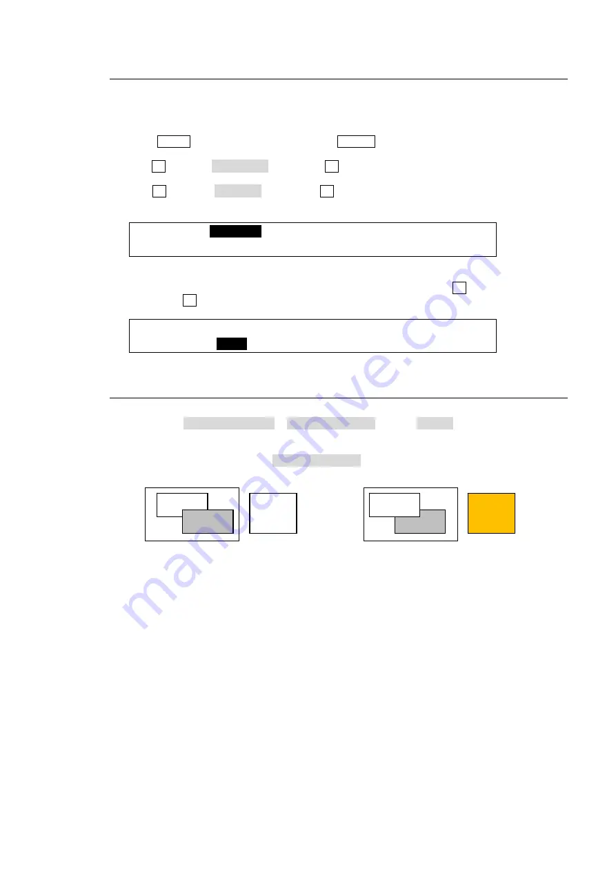
10-10. Changing KEY Layer Order
Layer order between KEY1 and KEY2, and KEY3 and KEY4 can be changed using a USER
button. Assign KEY1/2PRIORITY or KEY3/4PRIORITY (TYPE: KEYER) to a USER button.
See section 22. "USER Button."
Press the USER button, to which KEY1/2PRIORITY is assigned.
KEY1 appears in front of KEY2.
The KEY3/KEY4 layer order can be changed in the same way as that of KEY1/KEY2 order.
Also note that KEY3 and KEY4 layers are always placed in front of KEY1 and KEY2 layers.
USER
button
lit orange
USER
button
lit white
KEY1
KEY2
KEY2
KEY1


