


EN
- 5 -
12.-
P24V:
button that activates phantom power supply (24 V between pins 3 and 1, 2 and 1 of
the XLR connector) in the inputs INPUT 1-4. This allows the use of condenser microphones. Use this
switch with the volume at the minimum to avoid damage.
NOTA
: the phantom power supply must be activated in INPUT 1 to be able to use the
M-64
microphones.
13.-
GAIN
: gain controls to regulate the INPUT 1-4 signal levels.
14.-
PRIORITY MIC M-64 OUTPUT:
while messages are being sent from the
M-64
microphone a tension
of 24 V DC will be activated between the positive and negative terminals to activate the priority in
attenuators.
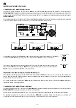
15.- Connection for FM antenna.
16.-
PRIORITY MIC M-64 INPUT 1
: connection for
M-64
microphones. Allows the connection of up to 3
microphones in cascade. Turn on PHANTOM power at INPUT 1 for
M-64
microphones to operate and
adjust their volume with the control designated to INPUT 1.
17.-
PAGING MIC MZ-648 INPUT 2
: connection for microphones
MZ-648.
Allows the connection of up to 3
microphones in cascade. Adjust the volume of these
MZ-648
microphones with the designated control
to INPUT 2.
18.-
LINK:
connection to connect expansion units.
19.-
DATA:
indicator of connected microphone activity.
20.-
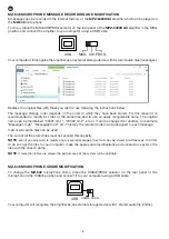
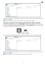
USB:
port to connect the switchboard to a computer to be able to update the audio files stored in the
amplifier. The switch has the following positions MSG/CHI/PROG:
-
MSG
: allows the messages stored in the amplifier’s internal memory to be modified in order to be
played from the
MZ-648
microphone.
-
CHI
: allows changing of the chime prior to the call stored in the internal memory of the switchboard,
so as to use it from the
M-64
microphone and the front panel CHIME button.
-
PROG
: device firmware upgrading.
21.-
EXTERNAL CONTROL CONNECTION MESSAGE BANK 1-6:
function not available.
22.-
POWER REMOTE
: close contacts to turn on the computer.
23.- For the AC power supply cable connection.
Summary of Contents for MPZ-6480RGU
Page 12: ...EN 12 BLOCK DIAGRAM...
Page 24: ...EN 24 ES DIAGRAMA DE BLOQUES...
Page 36: ...FR 36 DIAGRAMME FONCTIONNELS...
Page 48: ...PT 48 DIAGRAMA DE BLOCOS...
Page 50: ......
Page 51: ......
Page 52: ...www fonestar com...