background image

8.

Push the STOP button when the product is at

the distance you select to measure. The distance

shows in the display.

3.10.6.5 To disable or enable the Lawn Coverage

function
Disable or enable the 

Lawn Coverage

 function for each

area.
1.

Do steps 1–3 in 

To get access to the menu on

page 21

.

2.

Use the arrow buttons and the OK button to

move through the menu structure 

Settings > Lawn

Coverage > Area 1-3 > Disable

.

3.

Push the OK button.

4.

Push the BACK button.

3.10.6.6 To reset the Lawn Coverage settings
You can reset the 

Lawn Coverage

 settings for each area

and use the factory setting.
1.

Do steps 1–3 in 

To get access to the menu on

page 21

.

2.

Use the arrow buttons and the OK button to

move through the menu structure 

Settings > Lawn

Coverage > Area 1-3 > More > Reset

.

3.

Push the OK button.

3.10.7 Starting point

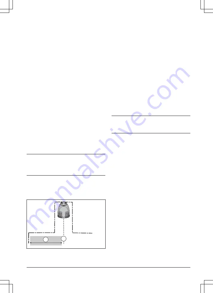
This function allows you to control how far the product

drives along the guide wire from the charging station

before it starts operating. The factory setting is 60 cm / 2

ft. and the maximum distance is 300 cm / 10 ft.

Note: 

The product straddles the guide wire from the

charging station to the starting point. Keep as short

distance to the starting point as possible to reduce the

risk of tracks forming on the lawn.

If the charging station is placed in a limited space area,

for example between flower beds, choosing a good

starting point is important so that the guide calibration

process is optimized. Refer to 

Guide calibration on page

21

.

B

A

A) Starting point

B) Minimum distance 60 cm / 2 ft (perpendicular to the

guide wire). If less distance, the calibration process is

interrupted. For the widest possible guide corridor, have

a minimum distance of 1.35 m / 4.5 ft. Refer to 

Guide

calibration on page 21

.

3.10.7.1 To set the starting point
1.

Do steps 1-3 in 

To get access to the menu on

page 21

.

2.

Use the arrow button and the OK button to move

through the menu structure 

Settings > Installation

> Starting point

.

3.

Use the arrow buttons to specify the distance in

cm.

4.

Push the BACK button.

3.10.8 Drive Past Wire function

The front of the product always moves past the

boundary wire by a specified distance. Then the product

moves rearward and changes direction. The factory

setting is 32 cm / 12 in. You can select a distance of

20-40 cm / 8-15 in.

Note: 

If you change the distance for 

Drive Past Wire

,

the distance will change along the boundary wire in all

parts of the work area.

3.10.8.1 To set the Drive Past Wire function
1.

Do steps 1–3 in 

To get access to the menu on

page 21

.

2.

Use the arrow button and the OK button to move

through the menu structure 

Settings > Installation

> Drive Past Wire

.

3.

Use the arrow buttons to set the distance.

4.

Push the BACK button.

3.10.9 Guide calibration

The guide calibration starts automatically when you

start the product for the first time. If you change

the installation of the product you can set the guide

calibration manually. Refer to 

Guide calibration on page

21

.

3.10.9.1 To do a new guide calibration
1.

Do steps 1–3 in 

To get access to the menu on

page 21

.

2.

Use the arrow buttons and the OK button to move

through the menu structure 

Settings > Installation

> Guide calibration

.

3.

Put the product in the charging station.

4.

Push the Start button to start the automatic

calibration.

1392 - 007 - 

Installation - 25

Summary of Contents for EasiLife

Page 1: ...Robotic Lawn mower EasiLife Operator s manual Easier by Design www flymo com uk ...

Page 2: ...e wire 20 3 8 To extend the boundary wire or the guide wire 20 3 9 After the installation of the product 20 3 10 To do the product settings 21 4 Operation 4 1 To use the ON OFF button 28 4 2 To start the product 28 4 3 Operating modes 28 4 4 To stop the product 29 4 5 To set the product to OFF 29 4 6 To charge the battery 29 4 7 Adjust the cutting height 29 5 Maintenance 5 1 Introduction maintenan...

Page 3: ...s when it is approaching the boundary wire The front of the product always passes the boundary wire by a specific distance before the product turns around When the product hits an obstacle or approaches the boundary wire the product selects a new direction The operator selects the operation settings with the keys on the keypad The display shows the selected and possible operation settings and the ...

Page 4: ...tment 10 Rating plate 11 Display 12 ON OFF button 13 Keypad 14 Cutting system 15 Blade disc 16 Handle 17 Chassis box with electronics battery and motors 18 Battery cover 19 Power supply 1 20 Loop wire for boundary loop and guide wire 21 Couplers for loop wire 22 Stakes 23 Connector for the loop wire 24 Screws for securing the charging station 25 Measurement gauge for help when installing the bound...

Page 5: ...ot be shortened extended or spliced Do not use a trimmer nearby the low voltage cable Be careful when trimming edges where the cables are placed 1 4 Symbols on the display The schedule menu is used to set when the product cuts the lawn The LawnSense function automatically adapts the cutting intervals to the grass growth The settings menu is used to set the general product settings The product will...

Page 6: ...lowing system is used in the Operator s Manual to make it easier to use Text written in italics is a text that is shown in the display or is a reference to another section in the Operator s Manual Text written in bold is one of the buttons on the product 6 Introduction 1392 007 ...

Page 7: ...tructure overview 1 Schedule Overview week Period 1 Period 2 Copy Su Current day All week Sa Fr Th We Tu Mo All days Reset Wizard Advanced LawnSense Low Mid High Cutting time Use LawnSense 1392 007 Introduction 7 ...

Page 8: ...t Security Lawn coverage Installation General Low Change PIN code New loop signal Security level Advanced Area 1 3 How How often How far Disable Reset Test More Starting point Drive past wire ECO mode Mower house High FrostSense Unit format PassageSense New pairing Remove paired device Bluetooth Guide calibration 8 Introduction 1392 007 ...

Page 9: ...icator lamp in the charging station on page 40 Use the ON OFF button B to switch on and switch off the product Use the GO button C to start the operation of the product Use the Menu button D to go to the main menu Note The Menu button is also used as a Back button to move up in the menu lists Use the Mode button E to select operating mode Use the OK button F to confirm the settings you select in t...

Page 10: ...ct to OFF before you clear a blockage do maintenance or examine the product and if the product starts to vibrate abnormally Examine the product for damage before you start the product again Do not use the product to it is defective If an injury or accident occur get medical aid Do not put power supply cable and extension cable in the work area This can cause damage to the cables Do not connect a d...

Page 11: ...duct when it is set to ON Use the park mode or set the product to OFF when persons especially children or animals are in the work area Refer to To set the product to OFF on page 29 Flymo recommends to set the product to operate when the work area has no activity The product can cause injury to animals at night in work area for example hedgehogs Refer to To set the schedule on page 21 Make sure tha...

Page 12: ...duct Push STOP and pull the product out of the charging station before lifting it To safely move from or within the work area 1 Push the STOP button to stop the product 2 Push the ON OFF button for 3 seconds and make sure the product is switched off Check that the indicator lamp on the keypad is not lit This means that the product is disabled Refer to Indicator lamp in the charging station on page...

Page 13: ...product performs It is therefore important to plan the installation carefully Make a blueprint of the work area and include all obstacles This makes it easier to see the ideal positions for the charging station the boundary wire and the guide wire Make a mark on the blueprint where to put the charging station the boundary wire and the guide wire Make a mark on the blueprint where the guide wire co...

Page 14: ...residual current device RCD with a tripping current of maximum 30 mA when you connect the power supply to the power outlet Low voltage cables of different lengths are available as accessories 3 4 3 To examine where to put the boundary wire CAUTION There must be a barrier of minimum 15 cm 6 in in height between the boundary wire and water bodies slopes precipices or public roads This will prevent d...

Page 15: ... stone is minimum 30 cm 12 in wide use the factory setting for the Drive Past Wire function to cut all the grass adjacent to the paving stone Refer to To set the Drive Past Wire function on page 25 If you make an island put the boundary wire that runs to and from the island near together E Put the wires in the same stake Refer to To make an island on page 16 Make an eyelet F where the guide wire i...

Page 16: ...and CAUTION Do not put a section of boundary wire across the other The sections of boundary wire must be parallel CAUTION Do not put the guide wire across the boundary wire CAUTION Isolate or remove obstacles that are less than 15 cm 5 9 in in height Isolate or remove obstacles that slope slightly for example stones trees or roots This will prevent damage to the blades of the product To make an is...

Page 17: ... guide wire D If less distance the calibration process is interrupted For the widest possible guide corridor have a minimum distance of 1 35 m 4 5 ft Refer to Guide calibration on page 21 Where the guide wire is connected to the boundary wire E Guide corridor F The product always runs to the left of the guide wire as seen facing the charging station Make sure that the guide wire has as much free a...

Page 18: ...h the screws to the ground until the guide wire is installed Refer to To install the guide wire on page 19 3 Connect the low voltage cable to the charging station 4 Put the power supply at a minimum height of 30 cm 12 in min 30 cm 12 5 Connect the power supply cable to a 100 240V power outlet Note When the charging station is connected it is possible to charge the product Put the product in the ch...

Page 19: ...e wire 1 2 cm 0 4 0 8 in above each connector 4 Push the guide wire through the slot in the charging station plate 5 Push the connector onto the metal pin on the charging station with the mark G1 6 Disconnect the charging station from the power outlet 7 Put the end of the guide wire at the eyelet on the boundary wire 8 Cut the boundary wire with a pair of wire cutters 9 Connect the guide wire to t...

Page 20: ...undary wire or the guide wire into position 5 Put the wire ends into a coupler Note Make sure that you can see the ends of the boundary wire or the guide wire through the transparent area of the coupler 6 Push down the cover on the coupler with adjustable pliers to attach the wires in the coupler 7 Put the boundary wire or the guide wire into position with stakes 8 Connect the charging station to ...

Page 21: ...n page 8 3 10 2 To get access to the menu 1 Push the STOP button 2 Use the up down arrow buttons and the OK button to enter the PIN code 3 Push the MENU button 3 10 3 To do the schedule settings You can set the schedule in 2 ways Set the schedule by using the wizard Refer to Wizard on page 21 Set the schedule in the Advanced menu Refer to To set the schedule on page 21 Note The lawn should not be ...

Page 22: ...the menu structure Schedule Advanced Overview Copy 3 Use the arrow buttons and the OK button to copy the schedule setting You can copy the schedule settings day to day or for the full week 3 10 3 5 To reset the schedule setting You can remove all schedule settings and use the factory setting 1 Do steps 1 3 in To get access to the menu on page 21 2 Use the arrow buttons and the OK button to move th...

Page 23: ...ct and the charging station In rare cases there may be a need to make a new signal for instance if two adjacent installations have very similar signals 1 Put the product in the charging station 2 Do steps 1 3 in To get access to the menu on page 21 3 Use the arrow buttons and the OK button to move through the menu structure Settings Security Advanced New loop signal 4 Wait for confirmation that th...

Page 24: ...e Area 1 3 3 Use the arrow buttons to select the area 4 Push the OK button 5 Measure the distance from the charging station to the beginning of the narrow passage Measure along the guide wire Refer to To measure the distance from the charging station on page 24 Note Make sure that the distance to the PassageSense is set inside the narrow passage 6 Push the arrow buttons to select the distance 7 Pu...

Page 25: ...e wire If less distance the calibration process is interrupted For the widest possible guide corridor have a minimum distance of 1 35 m 4 5 ft Refer to Guide calibration on page 21 3 10 7 1 To set the starting point 1 Do steps 1 3 in To get access to the menu on page 21 2 Use the arrow button and the OK button to move through the menu structure Settings Installation Starting point 3 Use the arrow ...

Page 26: ... steps 1 3 in To get access to the menu on page 21 2 Use the arrow buttons and the OK button to move through the menu structure Settings Installation FrostSense 3 Push the OK button to select FrostSense 4 Push the BACK button 3 10 13 Bluetooth The product can connect to mobile devices that have the Flymo EasiLife app installed Flymo EasiLife is a free app for your mobile device The short range int...

Page 27: ...hen push the BACK button 3 10 14 5 To reset all user settings 1 Do steps 1 3 in To get access to the menu on page 21 2 Use the arrow buttons and the OK button to move through the menu structure Settings General Reset all user settings 3 Use the right arrow button to select Proceed with reset of all user settings 4 Push the OK button to reset all the user settings Note Security level PIN code Loop ...

Page 28: ...roduct is in power save mode if the indicator lamp flashes Push the ON OFF button for 3 seconds to make the product active again The product is disabled when the indicator lamp is not lit 4 2 To start the product 1 Open the hatch to the keypad 2 Push the ON OFF button for 3 seconds The display is lit up 3 Use the up down arrow buttons and the OK button to enter the PIN code 4 Select the desired op...

Page 29: ...ith the GO button and is useful for quickly mowing an area where the grass has been mown less than in other parts of the yard You must manually move the product to the selected area Spot cutting means that the product mows in a spiral pattern in order to cut the grass in the area where it was started When this is done the product automatically switches back to Main area or Secondary area 4 4 To st...

Page 30: ...3 Turn the cutting height adjustment knob to select a cutting height a Turn clockwise to increase the cutting height b Turn counterclockwise to decrease the cutting height 30 Operation 1392 007 ...

Page 31: ...e a high pressure washer to clean the product Do not use solvents for cleaning Flymo recommends to use a special cleaning and maintenance kit as an accessory Speak to your Flymo service for more information 5 2 1 To clean the chassis and blade disc Examine the blade discs and blades weekly 1 Push the STOP button 2 Push the ON OFF button for 3 seconds to set the product to OFF Make sure that the LE...

Page 32: ...off the product 4 Check that the indicator lamp on the keypad is not lit 5 Turn the product upside down Place the product on a soft and clean surface to avoid scratching the body and the hatch 6 Remove the 3 screws Use a straight slot or cross tip screwdriver 7 Remove each blade and screw 8 Fasten new blades and screws 9 Check that the blades can pivot freely 5 4 Firmware update If service is done...

Page 33: ...r Torx 20 and remove the battery cover 6 Release the latch of the connector A and pull it upwards B A B CAUTION Do not pull the cables 7 Release the latch of the battery and lift up the battery B 8 Put the new battery into place in the product Note Fit the battery cover without clamping the cables If the seal on the battery cover is visibly damaged the entire battery cover must be replaced 9 Conne...

Page 34: ...Move the product and prevent the collection of water in the work area The grass is too high Cut the grass before you install the product Make sure that the grass is maximum 4 cm 1 6 in Trapped The product is behind a number of obstacles in a small area Remove the obstacles or put the boundary wire around the obstacle to make an island Refer to To make an island on page 16 Outside working area A se...

Page 35: ...ve The product has got caught in something and has been slipping Free the product and correct the cause of problem If it is because of wet grass wait until the lawn is dry before you use the prod uct The work area includes a steep slope Steep slopes must be isolated Refer to To examine where to put the boundary wire on page 14 The guide wire is not put diagonally in the slope Make sure that the gu...

Page 36: ...o do the schedule settings on page 21 The product has operated the maximum cut ting time for the day Usual operation of the product The time or date in the product is not correct Set the time or date Refer to To set the time date on page 26 Today s mowing completed The product has operated the maximum cut ting time for the day Usual operation of the product Refer to Make an estimate of the necessa...

Page 37: ...peak to your authorized service technician Connectivity problem Problem on the connectivity circuit board in the product Restart the product If the problem stays speak to your authorized service technician Connectivity settings restored The connectivity settings was restored be cause of a fault Do a check of the connectivity settings and change the settings if necessary Poor signal quality The con...

Page 38: ...harging station start the product and close the hatch A section of the boundary wire is across the other section of boundary wire to and from an island Install the boundary wire in the correct direc tion around the island Refer to To install the boundary wire on page 19 Problem with the pairing between the product and the charging station Put the product in the charging station and make a new loop...

Page 39: ...es Refer to To clean the charging plates and contact plates on page 31 If the problem stays speak to your Flymo service Settings restored A Reset all user settings has been done Usual operation of the product Guide not found The guide wire is not connected to the charg ing station Connect the guide wire to the charging sta tion Refer to To install the guide wire on page 19 Damage in the guide wire...

Page 40: ...ectly installed in the charging station Refer to To install the boundary wire on page 19 Damage in the boundary wire Find out where the damage is Replace the damaged section with new boundary wire Yellow flashing light The guide wire is not connected to the charg ing station Make sure that the guide wire is correctly installed in the charging station Refer to To install the guide wire on page 19 D...

Page 41: ...dule settings Refer to To reset the schedule setting on page 22 The product vibrates The cutting system is not in balance because of damaged blades Examine the blades and screws and replace them if necessary Refer to Replace the blades on page 32 The cutting system is not in balance because of too many blades in the same position Do a check that only one blade is attached to each screw Different t...

Page 42: ...ection of grass and clean the product Refer to Clean the product on page 31 6 6 Find breaks in the loop wire Breaks in the loop wire are usually the result of unintentional physical damage to the wire such as when gardening with a shovel In countries with ground frost also sharp stones that move in the ground can damage the wire Breaks can also occur due to the wire being stretched excessively dur...

Page 43: ... guide wire is connected to the boundary wire thick black line in the illustration Guide GUIDE L To rectify the fault you will need boundary wire connector s and coupler s a If the suspected boundary wire is short then the easiest way is to exchange all of the boundary wire between L and the point where the guide wire is connected to the boundary wire thick black line b If the suspected boundary w...

Page 44: ...ns which is the difference between a solid green light and a flashing blue light Then follow instruction in step 5 below 4 If indicator lamp still flashes blue in step 3 above Put L and GUIDE back in their original positions Then switch R and GUIDE If indicator lamp now is lit with a solid green light then disconnect L and connect a new boundary wire to L Connect the other end of this new wire at ...

Page 45: ... Keep the product in a dry frost free space Keep the product with all wheels on level ground during storage If you keep the charging station indoors disconnect and remove the power supply and all the connectors from the charging station Put the end of each connector wire in a connector protection box Note If you keep the charging station outdoors do not disconnect the power supply and the connecto...

Page 46: ...ption at maximum use 4 kWh month in a 500 m2 work area Charge current A DC 1 1 3 Type of Power Supply Unit2 ADP 40BR XX ADP 28EW XX FW7313 28 D XX Y 1 3 PI FW7313 28 D XX Y 1 3 ADP 28AR XX ADP 28AW XX FW7313 28 D XX Y 1 0 PI FW7313 28 D XX Y 1 0 Average mowing time min 65 Average charging time min 75 60 Boundary wire antenna Flymo EasiLife Operating Frequency Band Hz 100 80000 Maximum magnetic fie...

Page 47: ...erating frequency band MHz 2400 2484 Maximum transmitted power dBm 8 Husqvarna AB does not guarantee full compatibility between the product and other types of wireless systems such as remote controls radio transmitters hearing loops underground electric animal fencing or similar The products are made in England or the Czech Republic See information on the rating plate Refer to Introduction on page...

Page 48: ...the warranty Damage caused by water seepage from using a high pressure washer or from being submerged under water for example when heavy rain forms pools of water Damage caused by lightning Damage caused by improper battery storage or battery handling Damage caused by using a battery that is not a Flymo original battery Damage caused by not using Flymo original spare parts and accessories such as ...

Page 49: ...gulation Description 2006 42 EC Relating to machinery 2014 53 EU Relating to radio equipment 2011 65 EU Restriction of use of certain hazardous substances and that the following harmonized standards and or technical specifications are applied EN 60335 1 2012 AC 2014 A11 2014 A13 2017 EN 50636 2 107 2015 A1 2018 A2 2020 EN IEC 63000 2018 EN 61000 6 1 2007 EN 61000 6 3 2007 A1 2011 AC 2012 ETSI EN 3...

Page 50: ... I 2017 1206 The Radio Equipment Regulations 2017 S I 2012 3032 The Restriction of the Use of Certain Hazardous Substances in Electrical and Electronic Equipment Regulations 2012 and that the following harmonized standards and or technical specifications are applied EN 60335 1 2012 AC 2014 A11 2014 A13 2017 EN 50636 2 107 2015 A1 2018 A2 2020 EN IEC 63000 2018 EN 61000 6 1 2007 EN 61000 6 3 2007 A...

Page 51: ...1392 007 UK Declaration of Conformity 51 ...

Page 52: ...e names are registered trademarks of Flymo S A The Husqvarna UK policy of continuous improvement and updating means that specifications can be altered without prior notice All measurements quoted are approximate www flymo com uk F y l mo Original instructions 1142754 26 2022 01 10 ...

Reviews: