


Page 119
© 1998-2010 Fluke Calibration
4.
Remote Operation
4.1
Overview
Most of the PG9000 Terminal’s front panel functions can also be executed by commands from
a remote computer. The host computer can communicate with PG9000 using the COM1 RS232 port
or the IEEE-488 port located on the PG9000 Remote Electronics Module (REM) rear panel. The command
syntax is the same for either port except when using the IEEE STD. 488.2 Common commands.
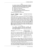
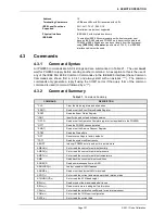
4.2
Interfacing
Sending a command to PG9000 places it in remote mode. The function keys on the front panel are
locked-out, except for the
[SYSTEM]
and
[AMBIENT]
keys which still respond to allow the user to change
the data displayed. Pressing the
[ESC]
key returns PG9000 to local mode unless the “REMOTE”
command was sent which locks out keypad operation until the “LOCAL” command is sent.
Most remote commands return a reply within 500 ms. The following commands may query external
devices connected to PG9000’s COM2 and/or COM3 ports and can take up to 5 to 10 seconds to reply:
“MASS=” (possible communications with an external AMH mass handler)
“PGEN=” (requires communications with an external pressure controller)
“SETUP=” (possible communications with external barometer or vacuum gauge)
“AMHLOAD=” (possible delay while AHM completes the action)
You must wait for this reply before issuing another command to PG9000. This ensures that PG9000 has
completed the command. An exception is the use of any of the IEEE STD. 488.2 Common Commands
(see Section 4.3.4.1) via the IEEE-488 interface (common commands all start with an asterisk, “*”). The
common commands only generate a reply if using the COM1 port or if the query form of the common
command is used (command followed by a “?”).
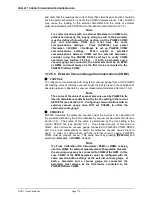
4.2.1
RS232 interface
To establish RS232 communications a standard pin-to-pin DB-9F to DB-9M RS232 cable
must be used to connect the host COM port to PG9000 COM1. The interface settings of both
ports must be the same.
Note
PG9000 supports an independent RS232 self-test to verify that the PG9000
RS232 ports are operating correctly and the interface cable being used is
valid. Use this self-test to troubleshoot if you are having difficulty
establishing communications with any PG9000 COM1 (see Section
3.12.5.3).
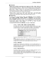
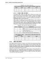
4.2.1.1
COM1
The PG9000 COM1 RS232 interface is located on the PG9000 Remote
Electronics Module (REM) rear panel. It is a 9-pin female DB-9F connector
configured as a DCE device. Data is transmitted out of PG9000 using pin 2, and
is received on pin 3. This allows a standard pin-to-pin DB-9M to DB-9F RS232
cable to be used to connect to a DTE host (see Table 19). Handshaking is NOT
required or supported.
COM1 RS232 commands must be terminated with at least a single carriage
return character, while line feed characters are ignored. All RS232 responses
from PG9000 are terminated with a carriage return character and a line feed
character (either
<CR><LF>
or
<LF><CR>
see Section 3.12.5.1).
Summary of Contents for PG9000 Series
Page 10: ...PG9602 OPERATION AND MAINTENANCE MANUAL 2011 Fluke Calibration Page X Notes...
Page 128: ...PG9602 OPERATION AND MAINTENANCE MANUAL 2011 Fluke Calibration Page 118 Notes...
Page 164: ...PG9602 OPERATION AND MAINTENANCE MANUAL 2011 Fluke Calibration Page 154 Notes...
Page 188: ...PG9602 OPERATION AND MAINTENANCE MANUAL 2011 Fluke Calibration Page 178 Notes...
Page 192: ...PG9602 OPERATION AND MAINTENANCE MANUAL 2011 Fluke Calibration Page 182 Notes...


