background image

Vertical flanged machines – Static clock

Measure using Static measurement mode

l

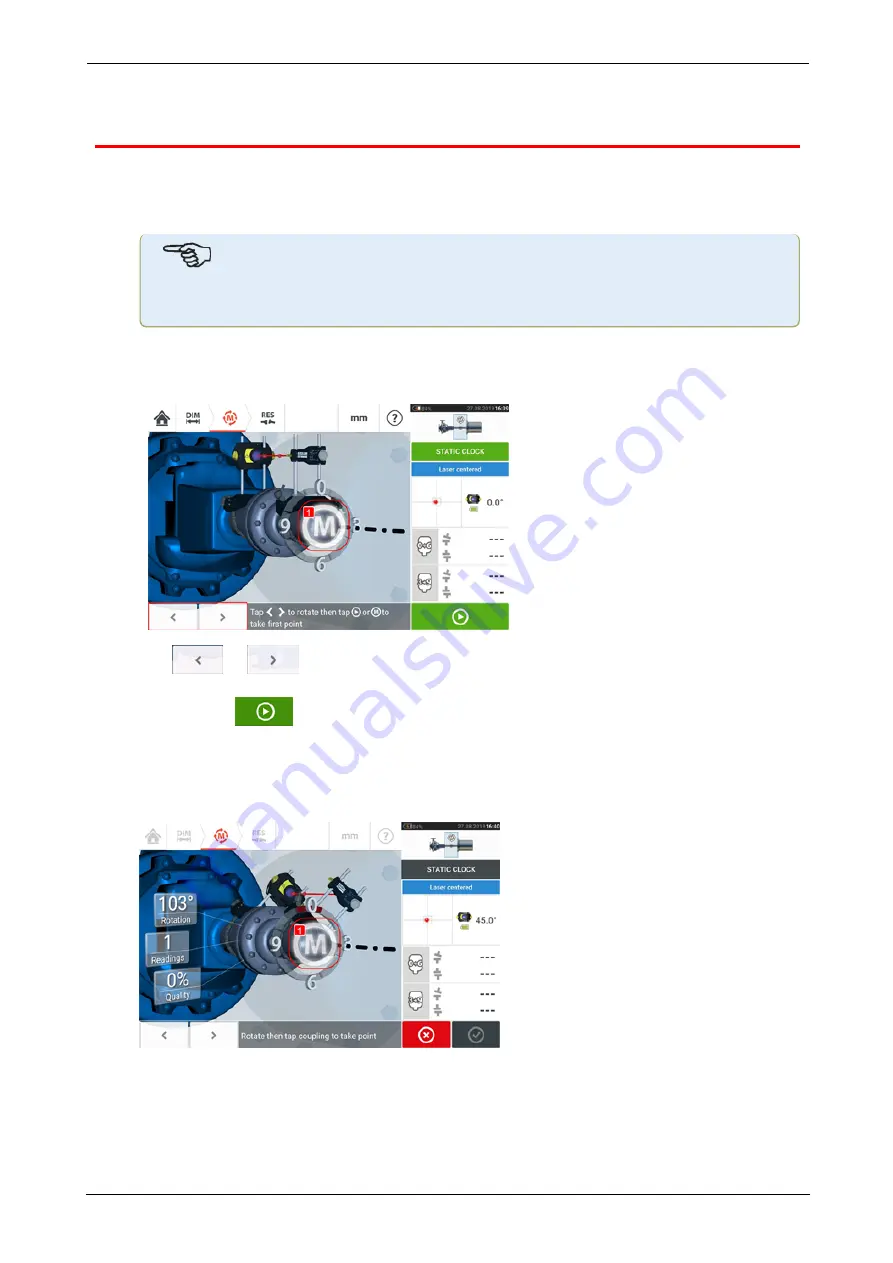
Center the laser beam.

Note

Static measurement mode is used for vertically mounted machines.                                 

l

Rotate the shafts to the first measurement position. If using the coupling housing num-
bering convention, the reference mark and the measurement position 0 should be
aligned or matched to each other.

l

Use

or

to position the displayed sensor and reflector at the angular rota-

tion corresponding to the actual position of the components mounted on the shafts, then

tap

M

(

1

) or

to take the first measurement point.

l

Rotate shaft to the second measurement position (e.g. 1:30). If the chosen meas-
urement position does not correspond to the angle selected automatically on the display,
use the navigation keys to manually position the sensor and reflector at desired angle on
the display. Take the measurement point by tapping

M

(

1

).

l

Take the maximum number of measurement points to maximize the quality of results.

SHAFTALIGN touch

103

On-board help

Summary of Contents for db PRUFTECHNIK SHAFTALIGN touch

Page 1: ...SHAFTALIGN touch On board help...

Page 2: ...SHAFTALIGN touch On board help Version 2 3 Edition 07 2020 Part No DOC 26 200 EN...

Page 3: ...e ment This document or parts thereof may not be reprinted or reproduced in any form without written permission of PR FTECHNIK SHAFTALIGN is a registered trademark of PR FTECHNIK Dieter Busch GmbH PR...

Page 4: ...Reflector 15 Sensor and reflector labelling 16 Home screen 18 Configuration 20 Built in camera 24 Gallery 24 RFID 26 Assigning a saved asset to an RFID tag 26 Opening an asset measurement assigned to...

Page 5: ...ances 44 Asymmetric and symmetric tolerances 45 Tolerance table based on coupling format 46 Suggested consolidated shaft alignment tolerances 46 Laser beam adjustment sensALIGN 3 49 Adjusting sensor a...

Page 6: ...Multiple feet results 76 Foot corrections 76 Live Move screen 78 Saving asset measurements 82 Saving an asset 82 Asset list options 83 Default template 87 Generating reports 89 Generating measurement...

Page 7: ...sensor firmware update 111 Updating sensor firmware to a newer version 111 Notification on sensor calibration 113 Best practice 116 Mounting sensor and reflector 116 Entering dimensions 116 Initializi...

Page 8: ...ng the question mark icon provided on the specific screen l 1 Tap to return to the start screen l 2 Tap to go back l 3 Tap to go to the opening page of this on board help l 4 Tap to go forward l 5 Tap...

Page 9: ...page to be able to access other related topics which are frequently used throughout the on board help Documentation Note This on board help and other relevant and related customer documents are saved...

Page 10: ...Components The main measuring components for shaft alignment are the rugged device the sensor and the reflector Rugged device SHAFTALIGN touch 9 On board help...

Page 11: ...iliary equipment such as a PC l 12 Magnetic strap used to hang device on any magnetic surfaces Note The only application running on this rugged device is Shaft Alignment and it runs in land scape mode...

Page 12: ...pplication may be exited and device switched to sleep mode by tapping the power off icon appearing in the home screen A hint requiring confirmation to go to sleep mode appears on the display Tap to co...

Page 13: ...et has been unused for extended periods Use only the supplied charger and corresponding USB C to USB A cable l Connect the standard USB A end 1 to the supplied USB charger l Plug the USB C end 2 to th...

Page 14: ...canning and when communication is established The sensor is water and dust resistant IP 65 The internal optics and electronics are intern ally sealed preventing possible contamination The sensor is po...

Page 15: ...FF Blinks orange when laser is in END position Blinks green when laser centered or in laser OK position When Bluetooth communication is established blinks blue once then red three times indicating las...

Page 16: ...lever flips into the horizontal position facing forward to hold the reflector in place on the bracket posts The reflector is adjusted by changing its vertical position and its horizontal angle using t...

Page 17: ...ol label is affixed on the front of the sensor l 2 On the back of the sensALIGN 3 sensor is an amalgamation of three labels The top label shows the laser safety warning The lower label contains the se...

Page 18: ...T121 Contains Rechargeable Lithium Ion Battery 3 7 V 5 Wh R 209 J00171 MSIP CRM BGT BT121 l 3 The label affixed on the back of the reflector The following text is found on the label S No XXXX XXXX Ope...

Page 19: ...Soft foot icon is used to access soft foot measurement l 3 The Vertical alignment icon is used to access the vertical alignment application If this icon is inactive tap the New asset icon 5 to activa...

Page 20: ...rom the Cloud drive l 12 The Configuration icon is used to configure the Shaft application settings which include language date time default settings and access its built in mobile con nectivity Mobil...

Page 21: ...ons used to manage the power usage in the touch device The four power modes available are Standard the display dims after 10 minutes and goes to sleep mode after 20 minutes Maximum no dimming and no s...

Page 22: ...creens The Dimensions screen uses only positive integers The set time zone is coupled to the default RPM unless the default RPM is edited independently Setting the time zone to say Central America res...

Page 23: ...sers to login l Sensor list displays all available sensors l The About screen displays the device serial number firmware version of the applic ation and available memory space The applicable GNU Gener...

Page 24: ...SHAFTALIGN touch 23 On board help...

Page 25: ...the Take picture icon to take a photo of the object focused on the display l 3 Tap this location to access the device gallery All images taken using the touch device are saved at this location l 4 Obj...

Page 26: ...eleted by tapping the trash icon 1 The images in the gallery may be scrolled by using the arrow icons 2 3 Note Images saved to the gallery may only be transferred to a PC if assigned to an asset Befor...

Page 27: ...rrect asset automatically Assigning a saved asset to an RFID tag From the home screen tap the Asset park icon to display assets saved Tap the asset 1 that is to be assigned to the RFID tag then tap th...

Page 28: ...d already been assigned to the RFID tag a hint requesting over writing of the data appears Opening an asset measurement assigned to an RFID tag From the home screen tap the RFID icon Position the rugg...

Page 29: ...ent The asset name is displayed on the home screen Tap the shaft alignment icon 1 to start the application Note If however no data had been written on the RFID tag a hint on missing information appear...

Page 30: ...drive After finalizing a measurement save the asset 1 then upload it to Cloud drive Tap the Upload icon 2 The asset appears in ARC 4 0 Exchange view with the status com plete Drag and drop the asset i...

Page 31: ...ration supplied by PR FTECHNIK for example do not use support posts longer than those supplied with the bracket l A Anchor peg l Choose the shortest support posts which will still allow the laser beam...

Page 32: ...sts Note the orientation of the sensor The micro USB port must be at the top l Clamp the sensor onto the support posts by tightening the yellow knobs Ensure that the laser beam can pass over or throug...

Page 33: ...ge later on The bottom of the knob should be flush with the arrow marking on the reflector housing M Arrow marking Match the height of the yellow knob approximately to the tip of the arrow l Flip up t...

Page 34: ...ey should also visually appear to be rota tionally aligned to each other In some cases if the coupling is large enough a coupling bolt can be removed and the laser beam shot through the bolt hole Make...

Page 35: ...te If units are set to Imperial system inch fractions may be entered as follows For 1 8 enter 1 8 0 125 For 10 3 8 enter 10 3 8 10 375 The coupling diameter value may be determined by entering the mea...

Page 36: ...the machine carousel up or down and select desired machine Position desired machine at the centre of the carousel then tap to confirm selection and return to the dimen sions screen Toggle Toggle is u...

Page 37: ...erature between the idle and operating conditions Access the thermal growth screen by tapping the item Thermal growth Thermal growth values can be entered only when machine feet have been defined To e...

Page 38: ...calculate thermal growth compensation if no other values are avail able Thermal growth is calculated from the material coefficient of linear thermal expansion expected temperature difference and lengt...

Page 39: ...abled 4 the corresponding machine within the mini train inset at the top right corner appears in orange 5 Tap to simultaneously display the calculated thermal growth value for the respective feet pair...

Page 40: ...iate machine feet are not displayed in the dimension screen Tap to add any intermediate feet l The intermediate feet pair is added after the front feet l Enter this dimension in the row that appears l...

Page 41: ...use with CNC machines In this format the length between the two shafts must be entered Targets Targets are misalignment values specified as an offset and an angle in two perpendicular planes horizonta...

Page 42: ...After target values have been entered tap to proceed SHAFTALIGN touch 41 On board help...

Page 43: ...s RPM When the coupling type is spacer the tol erance table values are determined by the length of the spacer shaft and the RPM Tolerances are accessed via the dimensions screen Tap the coupling 1 the...

Page 44: ...tolerance table 4 ANSI standard specification tolerances The Acoustical Society of America ASA developed shaft alignment tolerances for both short flex and spacer couplings on standard rotating machi...

Page 45: ...lerances 2 can be activated only when user defined tolerances are enabled In asymmetric tolerances the tolerance values for the two coupling planes are not the same Tap 3 to edit user defined toleranc...

Page 46: ...not been enabled 1 the displayed specified tolerances 2 are symmetric The gap and offset tolerances for both horizontal and vertical planes are identical If asymmetric tolerances are enabled 3 all fou...

Page 47: ...g and 2 is angle offset for short flex coupling Change coupling format by tapping 3 Note There are no tolerance tables for consolidated spacer shaft coupling formats Con solidated formats consider the...

Page 48: ...2 5 4 1500 0 07 0 04 6 7 4 5 1800 0 06 0 04 5 7 3 8 3000 0 04 0 02 3 7 2 5 3600 0 03 0 02 3 1 2 1 6000 0 02 0 01 2 0 1 3 7200 0 02 0 01 1 7 1 1 Offset 600 0 23 0 13 9 0 5 1 750 0 18 0 10 7 3 4 1 900...

Page 49: ...00 mm spacer length or per 1 of spacer length 600 0 30 0 18 3 0 1 8 750 0 24 0 14 2 4 1 4 900 0 20 0 12 2 0 1 2 1000 0 18 0 11 1 8 1 1 1200 0 15 0 09 1 5 0 9 1500 0 12 0 07 1 2 0 7 1800 0 10 0 06 1 0...

Page 50: ...e laser beam 2 Leave the reflector dust cap on If the sensor and reflector have been roughly positioned to each other during mounting the laser beam should strike the reflector dust cap and is readily...

Page 51: ...orrection is necessary if the laser beam is too far left or right 4 Remove the reflector dust cap so that the laser beam strikes the reflector and is reflected back to the sensor The sensor laser beam...

Page 52: ...which movement should take place l The wizard arrows next to the vertical position adjustment thumbwheel 1 and the hori zontal adjustment knob 2 indicate the direction and magnitude in which the thum...

Page 53: ...improves disappearing completely once the laser beam is centered l Measurement may commence once the laser beam is centered 52 Version 2 3 On board help...

Page 54: ...lute X Y coordinates of the laser beam on the position detector the angle at which the sensor is currently positioned on the shaft and the sensor serial number Center the laser beam dot on the positio...

Page 55: ...of the values Tap Absolute to return to the absolute values Note that the menu items on the screen may be used to display following items Sensor list displays serial number of sensors detected or prev...

Page 56: ...the menu item Sensor list Tap menu item Sensor list 1 to view scanned sensors The hint Scanning for sensor s 2 appears during the scanning process As soon as the sensor is detected it is listed down...

Page 57: ...ata points are clustered around the average of those data points It is a measure of the measurement calibre The smaller the SD the better the quality of the data collected Measurement quality is a fac...

Page 58: ...hite metal bearings and journal bearings Set the averaging by tapping the Averaging button 1 A scale 2 used to set the averaging value appears on the screen Tap desired averaging value which then appe...

Page 59: ...asurement points is required to determine the alignment condition but more measurement points over a wider rota tional angle is recommended Note The default number of Active Clock measurement points i...

Page 60: ...ble sectors The desired number of measurements points is set in Configuration under Default settings Three measurement points are sufficient to determine the alignment condition Once the laser beam ha...

Page 61: ...refore the hint 2 to take a further meas urement point Note Coupling results 3 are displayed because three measurement points are sufficient to determine the alignment condition Note As shafts are rot...

Page 62: ...n has been activated The item Default settings is found under Configuration The initial measurement is taken by tapping either the pulsating M or after sta bilization When the rotational angle of the...

Page 63: ...62 Version 2 3 On board help...

Page 64: ...e 12 00 1 30 3 00 4 30 6 00 7 30 9 00 or 10 30 o clock position viewed from reflector towards sensor Position shaft as accurately as possible using either an external inclinometer or protractor Tap t...

Page 65: ...ded l 1 Rotational arc showing rotational angle covered by the shafts during measurement The color of the arc sectors shows the attained measurement quality 4 l 2 Rotational angle completed by the sha...

Page 66: ...accessing the XY view before Laser End is displayed l If the laser dot 1 on the display continues to move further away from the center of the detector screen while rotating shafts to take measurements...

Page 67: ...p 1 to proceed to results then 2 to view results Note If taking measurements using the Active Clock mode it is recommended to take all set active measurement points Once all set points are taken the r...

Page 68: ...nment and any Live Move measurements taken on the current couplings Access the measurement table by tapping either the results repeatability table 1 or coupling results 2 3 The following items are inc...

Page 69: ...not selected l 2 Measurements in chronological order l 3 Used measurement mode l 4 The rotational angle covered during measurement l 5 Vertical and horizontal gap and offset values l 6 Measurement qua...

Page 70: ...asurement table Measurement quality Measurement quality is depicted using the following colour codes Blue excellent Green acceptable Yellow not acceptable Red poor Measurement quality is based on the...

Page 71: ...ertia abrupt changes in the measurement rotation speed e g releas ing and re applying a break during the rotation l Rotation direction change in the measurement rotational direction l Rotational speed...

Page 72: ...red measurement 1 then tap 2 to access the measurement data screen Broken ellipse The deviation diagram used with the rugged device is referred to as broken ellipse During measurement the laser beam t...

Page 73: ...lected point is inactive The point is made active by tapping Activate l 8 Shows coupling results with a measurement point deactivated In this example one measurement point has been deactivated l 9 Wit...

Page 74: ...ain Manager Train Setup Train Fixation screen Note Only Train Fixation is active l 11 Alignment condition tolerance symbol In the results screen the three icons dimensions measurement and results are...

Page 75: ...ults l 4 Horizontal coupling results l 5 Selected results mode l 6 Alignment condition tolerance symbol l 7 Horizontal and Vertical foot results in 2 D Results options Alignment results may be display...

Page 76: ...ified coupling targets or machine thermal growth and is the default view It is the option that should be used when actually performing alignment corrections Sign convention Coupling gap is positive wh...

Page 77: ...multiple feet screen In 2D the multiple feet screen is accessed by tapping the machine centerline 1 Note If the machine intermediate feet were already defined within machine properties then the foot...

Page 78: ...dimension between the front feet and the intermediate feet in the row that appears then tap The foot correction values for the intermediate feet appear in the corresponding row SHAFTALIGN touch 77 On...

Page 79: ...r removing shims whereas the vertical condition is less prone to being affected when performing horizontal moves It may be necessary to recheck soft foot before proceeding Live Move is monitored in ei...

Page 80: ...laser beam is centered the Live Move screen appears l 1 The selected Live Move plane in this example H horizontal l 2 Arrows indicate direction and magnitude to move machine feet l 3 Tolerance coded g...

Page 81: ...arefully to ensure that machine end and direction moved are correct The smiley on the display screen gives an indication of the alignment status as the machine is moved Machines should be moved to wit...

Page 82: ...ew V is selected when the function Live Move function is started only the vertical condition will be displayed Likewise if the horizontal view H is selected then only the horizontal condition will be...

Page 83: ...sults screen To save an asset measurement tap the menu item Save then use the onscreen keyboard to enter the measurement file name Once asset name has been entered tap to save the asset under Asset pa...

Page 84: ...has been opened but the alignment measurement has not been completed l This icon shows that the alignment measurement has been completed Asset list options By tapping the respective icon the followin...

Page 85: ...d to edit directly the name of the selected asset Once completed tap The asset will now appear in the asset list with the new name l 5 Used to create a template A template is a file that serves as a p...

Page 86: ...Tap to save the asset as a template Enter name of template then tap l Note If for any given reason the template is not to be saved tap the cancel icon to cancel saving SHAFTALIGN touch 85 On board hel...

Page 87: ...is open and running in the background The symbol serves the dual purpose of either opening the selected asset or saving any changes that may have been applied to the asset but not yet saved If an asse...

Page 88: ...able templates are listed on the template list Select template to be designated as default then tap 1 The default template now appears on the template list with a check mark 1 To revert the default te...

Page 89: ...Note If no template is selected all template list options are unavailable 88 Version 2 3 On board help...

Page 90: ...screen opens In this example none of the Generating report menu items has been activated To activate any of the items tap the respective icon When Machine alignment information is activated useful ma...

Page 91: ...ia SHAFTALIGN touch Tablet Media Reports l Note The generated PDF report saved together with the asset may also be accessed via the software platform ARC 4 0 in Asset Attachments l 10 Tap to save any...

Page 92: ...he report logo gallery opens l From the report logo gallery tap the desired logo and then tap The selected logo will now appear on the PDF measurement report when Show report logo is activated Note Th...

Page 93: ...he Generating report screen opens The hint Pen drive plugged appears Tap If the USB drive had been previously used to save reports from the given rugged device the hint below appears Tap to confirm sa...

Page 94: ...onnected USB drive in this example USB4REPORTS The files and folders in the connected USB drive will be displayed Note The displayed folders may be created in advance from a PC Tap the desired folder...

Page 95: ...checked before aligning the shafts This can be done quickly and con veniently with the aid of the soft foot function With the sensor and reflector mounted on the shaft in the usual way the system is a...

Page 96: ...are parallel soft foot angular soft foot and induced soft foot There are instances where the soft foot is a combination of two or more types Checking for soft foot is part of machine and job preparati...

Page 97: ...t the components enter all required dimensions and then adjust the laser beam as required You may refer to Mounting components Dimensions and Laser beam adjustment Activate sensor measurement by swipi...

Page 98: ...cel icon The above soft foot measurement procedure is repeated for all four feet positions The smiley indicates the soft foot condition A happy smiley indicates that the measured soft foot is within t...

Page 99: ...t using feeler gauges The calculated values are then entered in the soft foot application Manual values do not require use of either sensor or reflector Swipe the green button to Manual Manual entries...

Page 100: ...orrected by positioning the flange laterally l 1 Sensor l 2 Reflector prism The sensor and reflector are mounted on either side of the coupling as for horizontal machines The sensor is mounted on the...

Page 101: ...hosen start point Number the points counterclockwise as seen from sensor to reflector beginning with 0 first followed by 1 30 3 00 4 30 6 00 7 30 9 00 and 10 30 For circular housings measure the circu...

Page 102: ...following required machine dimensions l 1 Sensor to reflector l 2 Sensor to coupling center This dimension is calculated as half the sensor to reflector distance automatically The dimension may be edi...

Page 103: ...ppears l Tap the respective value boxes then use the onscreen keyboard to enter flange dimen sions and bolt pattern lengths The number of bolts is edited by tapping 1 then entering the value directly...

Page 104: ...sensor and reflector at the angular rota tion corresponding to the actual position of the components mounted on the shafts then tap M 1 or to take the first measurement point l Rotate shaft to the se...

Page 105: ...e The colour of the Proceed icon denotes the attained measurement quality Note If flange dimensions have not been defined the flange icon appears Tap to enter missing flange dimensions l Tap to view m...

Page 106: ...re active and may be used anytime Shimming modes Shimming modes are defined as follows l 1 mode indicates all positive shimming l 2 mode indicates zero plus shimming In this mode one bolt position is...

Page 107: ...rom the reflector towards the sensor Note The little clock face on the sensor serves as a reminder of the viewpoint WARNING When the sensor is switched on the laser beam is emitted DO NOT stare into t...

Page 108: ...ble 2 Angularity corrections are made by shimming The shimming values at the respective bolt positions are shown on the screen Insert or remove shims with the correct thickness under the selected bolt...

Page 109: ...d sensor at the desired 45 position This pos ition corresponds to the actual angular position of the sensor and reflector on the shafts Tap to confirm position A hint to select desired Live Move direc...

Page 110: ...ondition and Red poor condition The color of the arrows changes with the movements automatically Monitor the arrows on the Live Move screen l Corrections should be brought as close as possible to zero...

Page 111: ...xcellent tolerance or an OK icon acceptable tolerance tighten the flange bolts then tap to remeasure and check to confirm if the new alignment condition is in tolerance 8 If not repeat the above steps...

Page 112: ...ected via Bluetooth to the rugged device a sensor firmware update notification appears on the display It is recommended to update the sensor firmware Tap to proceed to update the sensor The following...

Page 113: ...nsor has now been updated to the newer version available on the rugged touch device Tap to exit the update screen The new sensor firmware version appears under Sensor properties which is accessed by t...

Page 114: ...the older sensor firmware version Tap UPDATE to proceed with the sensor firmware update Note The sensor firmware update notification continues to appear once everyday until the firmware update is comp...

Page 115: ...representative for assist ance or visit www pruftechnik com Note The calibration due date is also found under Sensor properties If the calibration due date has expired the due date will be highlighte...

Page 116: ...ration due date has expired and the sensor is connected via Bluetooth to the rugged touch device a calibration expiry notification appears on the display Tap to close the notification SHAFTALIGN touch...

Page 117: ...ensions l Dimensions measured to within 3 mm 1 8 in using a tape measure with 1 mm or 1 32 in divisions are acceptable l When entering the dimension between the front and back feet use the distance be...

Page 118: ...ring and between measurements l Mounted components moved during shaft rotation l Uneven shaft rotation l Change in temperature within machines l External vibration from other rotating machines Results...

Page 119: ...esentative or PR FTECHNIK Condition Monitoring l Download the update file to the desired directory on a PC l Switch the rugged device on then connect it to the PC A hint to allow the Windows PC access...

Page 120: ...te file has been copied to the FirmwareUpadte folder disconnect the rugged device from the PC The following hint appears l Note DO NOT tap the device or press any of the hard keys Wait for the next hi...

Page 121: ...efly Power off and Restart icons appear on the display l Tap Restart The update is now completed and may be checked and confirmed in the about menu item in configuration after the restart Documentatio...

Page 122: ...Hz 5 GHz Bluetooth Version 4 2 RFID Camera Main Camera Resolution 8 0 MP Auto Focus Front Camera Resolution 5 0 MP Environmental protection IP68 dustproof submersible 1 5 m Temperature range Operation...

Page 123: ...e 20 C to 60 C 4 F to 140 F Dimensions Approx 105 x 69 x 55 mm 4 9 64 x 2 23 32 x 2 11 64 Weight Approx 210 g 7 4 oz with dust cap Detector Measurement range Unlimited dynamically extendible US Patent...

Page 124: ...y and general information document Technical data Reflector prism Reflector prism Type 90 roof prism Accuracy avg 99 Environmental protection IP 67 submersible dustproof Temperature range Operation 20...

Page 125: ...rtical alignment 107 Coupling backlash 117 Coupling torsion play 59 D Default measurement mode 59 Default settings 20 Device interface 11 Documentation 120 E Extend 65 Extend measurement range 65 F Fi...

Page 126: ...94 Soft foot correcting 95 Soft foot manual entry 98 Soft foot parallel 94 Spacer shaft 40 Standard deviation 56 68 Static Clock 56 63 Static measurement 58 Static measurement mode 79 Status envelopes...

Page 127: ...W Wireless connection 21 X XY view 81 XY View 53 SHAFTALIGN touch 126 On board help...

Reviews: