7
Digital Communication Interface
To control the furnace through a computer, follow the instructions listed below.
The program supplied is a demo program and may be altered by you for your
specific needs.
First make the appropriate cable assembly for your computer system. The serial
communications cable attaches to the calibrator through the DB-9 connector at
the back of the instrument.
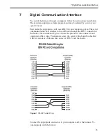
Figure 4
shows the pin-out of this connector and
suggested cable wiring. To eliminate noise, the serial cable should be shielded
with low resistance between the connector (DB-9) and the shield.
Connect the appropriate connectors to your computer and to the furnace. To
communicate with the furnace:
25
7 Digital Communication Interface
Figure 4
RS-232 Cable Wiring


