


9100A-017
5-2
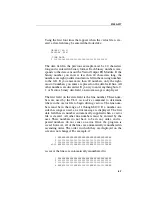
Figure 5-1. Vector I/O Control
NOTE
If an external stop signal has been received and is
enabled, the vector driving terminates, but drive-
poll does not indicate vector driving as complete.
EDGEOUTPUT
5.4.
The
edgeoutput
function sets the signal edges for triggering the
START, STOP, and DR CLK lines. Note that the START and
STOP lines are in common with the receive side of the module,
but can have separate edge control. The START edge can also be
set to “at_vectordrive”, which means that no external start signal
is required to begin driving out vectors.
Summary of Contents for 9100A Series
Page 6: ...vi ...
Page 8: ...viii ...
Page 10: ...x ...
Page 14: ...9100A 017 1 4 ...
Page 24: ...9100A 017 3 6 ...
Page 44: ...9100A 017 5 4 ...
Page 58: ...9100A 017 6 14 ...
Page 83: ...A 1 Appendix A New TL 1 Commands ...
Page 84: ...9100A 017 A 2 ...
Page 87: ...clockfreq 3 For More Information The Overview Of TL 1 section of the Programmer s Manual ...
Page 88: ...clockfreq 4 ...
Page 91: ...drivepoll 3 For More Information The Overview Of TL 1 section of the Programmer s Manual ...
Page 92: ...drivepoll 4 ...
Page 104: ...vectordrive 4 ...
Page 107: ...vectorload 3 For More Information The Overview Of TL 1 section of the Programmer s Manual ...
Page 108: ...vectorload 4 ...
Page 116: ...9100A 017 C 2 ...
Page 117: ...9100A 017 C 3 ...
Page 118: ...9100A 017 C 4 ...


