Preparing for Operation
Instrument Preparation
2
2-17
When using the totalizer with time stamps in computed channels (e.g. rate
calculations), the timestamp interval may vary depending on the number of active
channels, number of active modules, and number of alarms.
Totalizer Enable
Σ
en is an input that can be used to enable or disable the totalizer counting
capability. In the default, unconnected state, the totalizer is enabled (high). Pulling
Σ
en low with a logic low input or contact closure to signal ground disables
totalizer counting.
Relays
The relay contacts consist of 8 Double Pole/Single Throw (DPST) relays that can
be used to provide added isolated IO connections or switch low power. See Table
A-39 in Appendix A for complete specifications.
Controls and Indicators
The front panel provides a display and a set of control keys; the rear panel
provides the power switch and Ethernet status indicators. See Figures 1-2 through
1-4 for an overall view of front and rear panels, and Front Panel Operating
Procedures later in this chapter for procedures that use the front and rear panel
controls and indicators.
Front Panel Controls
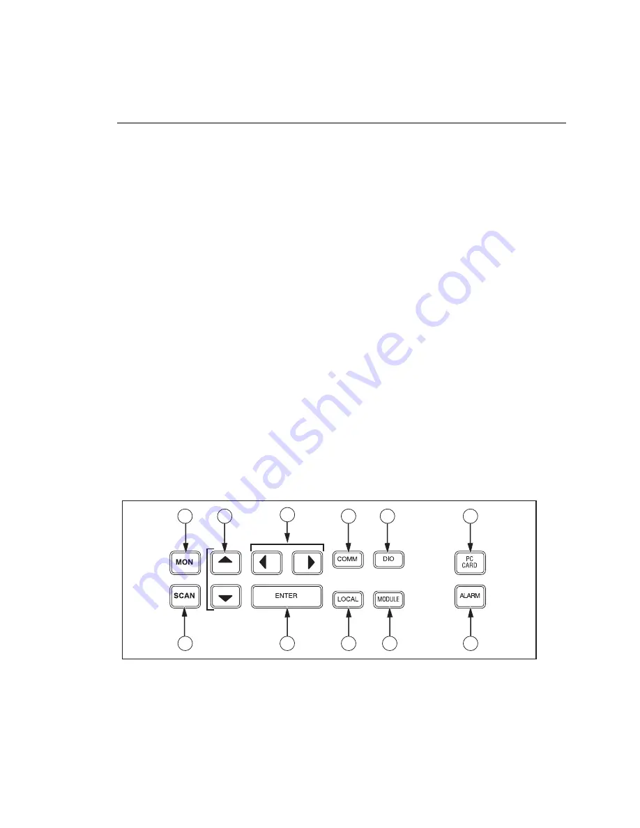
Use the front panel controls (Figure 2-8) to enter configuration parameters, and
choose monitoring functions. Table 2-1 summarizes the front panel control
functions.
11
10
9
8
7
1
1
1
2
3
4
5
6
alg01f.eps
Figure 2-8. Front Panel Controls
Summary of Contents for 2680A
Page 8: ......
Page 14: ...2680A 2686A Users Manual vi ...
Page 20: ...2680A 2686A Users Manual 1 2 ...
Page 98: ...2680A 2686A Users Manual 2 62 ...
Page 196: ......
Page 228: ...2680A 2686A Users Manual A 32 ...
Page 236: ...2680A 2686A Users Manual C 4 ...
Page 242: ...2680A 2686A Users Manual D 6 ...
Page 274: ...2680A 2686A Users Manual 6 ...

