2680A/2686A
Users Manual
4-20
Analog Channel Integrity Test
The following procedure tests the integrity of each analog channel (2 to 20) to
verify each analog channel is capable of making measurements.
1.
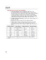
Configure Channel for Ohms
Using the Fluke DAQ software, configure
channels 2 (then 3, then 4, etc. as this step is repeated) to 20 for Ohms 2W,
300 range [PAI] or 30 k range [FAI].
2.
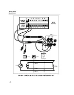
Connect Test Leads
Remove the Universal Input module from the
instrument, disconnect the test leads and connect them to the channel under
test (starting with channel 2). Reinstall the Universal Input module in the
instrument.
3.
Open Spy
Open the Spy window under the Configuration dialog.
4.
Verify Reading
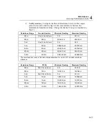
Alternately open and short the test leads observing the
measurement for the analog channel under test in the Spy window shows
Overload for opened leads and very low resistance for shorted leads (less than
10
Ω
for the PAI, or less than 1 k
Ω
for the FAI).
5.
Repeat Test for each Channel
Repeat steps 2 to 4 for each channel (3, 4, 5,
and so forth to channel 20).
Open Thermocouple Response Test
This test checks the Open Thermocouple response.
1.
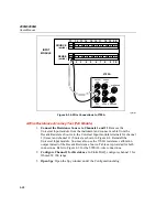
Connect an 820 Ohm Test Resistor
Remove the Universal Input module
from the instrument and connect an 820
Ω
resistor to the channel 1 terminals.
Reinstall the Universal Input module.
2.
Configure Channel 1 for Thermocouples
In Fluke DAQ, configure channel
1 for Thermocouples with Range (thermocouple type) K.
3.
Open Spy
Open the Spy window under the Configuration dialog.
4.
Connect a 10 k Ohm Test Resistor
Remove the Universal Input module
from the instrument and connect a 10 k
Ω
resistor to the channel 1 terminals to
simulate an open thermocouple condition. Reinstall the Universal Input
module.
5.
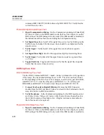
Verify Open Thermocouple
The Spy window indicates an open
thermocouple detect condition by displaying Open TC in place of a
temperature reading.
Summary of Contents for 2680A
Page 8: ......
Page 14: ...2680A 2686A Users Manual vi ...
Page 20: ...2680A 2686A Users Manual 1 2 ...
Page 98: ...2680A 2686A Users Manual 2 62 ...
Page 196: ......
Page 228: ...2680A 2686A Users Manual A 32 ...
Page 236: ...2680A 2686A Users Manual C 4 ...
Page 242: ...2680A 2686A Users Manual D 6 ...
Page 274: ...2680A 2686A Users Manual 6 ...

