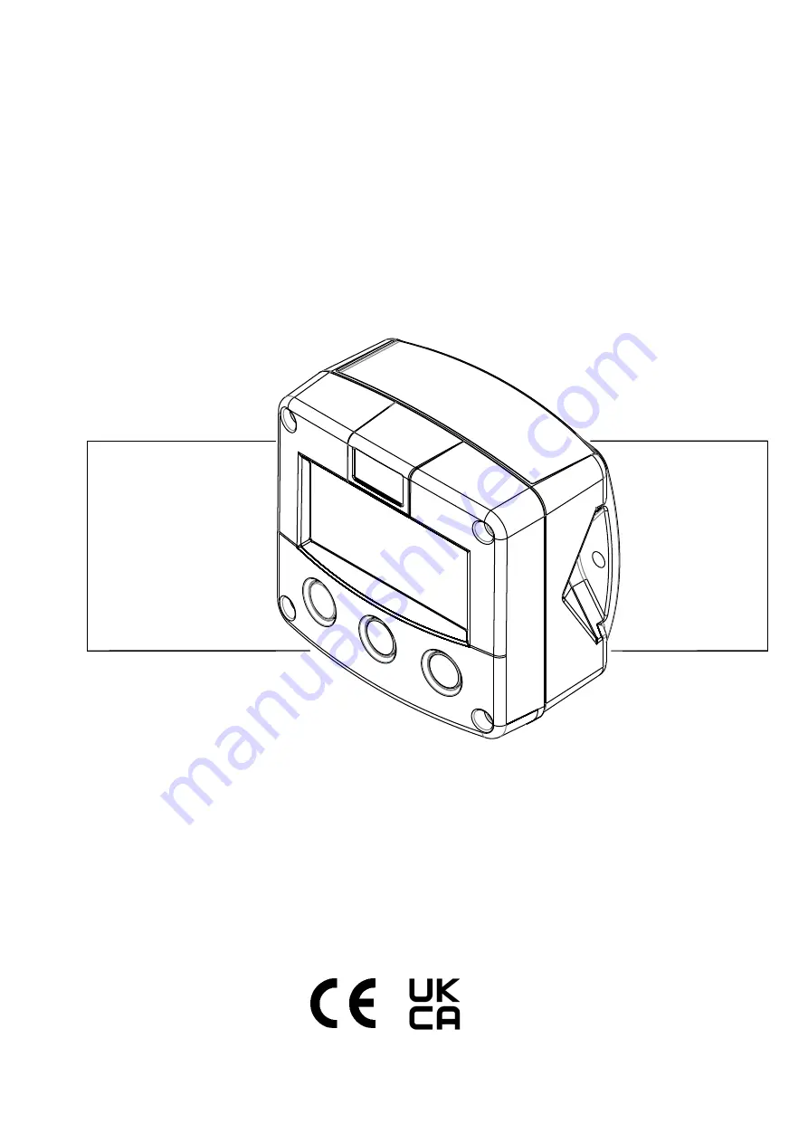
Fluidwell F043-T Manual Download Page 1

F043-T 

TEMPERATURE MONITOR 

WITH HIGH / LOW TEMPERATURE ALARMS 


Signal input sensor: Pt100  

Alarm output: one temperature alarm 

Options: Intrinsically Safe 


F-Series - Field mounted indicators for safe and hazardous areas. 

More info: www.fluidwell.com/fseries


Summary of Contents for F043-T

Page 1: ...TOR WITH HIGH LOW TEMPERATURE ALARMS Signal input sensor Pt100 Alarm output one temperature alarm Options Intrinsically Safe F Series Field mounted indicators for safe and hazardous areas More info ww...

Page 2: ...ot be disposed of into the general waste system or into a landfill At the end of its life equipment shall be disposed of according to the local regulations regarding waste of the electrical and the el...

Page 3: ...amage of the F043 T or connected instruments A caution indicates actions or procedures which if not performed correctly may lead to personal injury or incorrect functioning of the F043 T or connected...

Page 4: ...g conditions 15 4 3 Handling the F Series enclosure 16 4 3 1 Identification 16 4 3 2 Opening Removing the cover 17 4 3 3 Closing Replacing the cover 17 4 4 Mechanical installation 18 4 4 1 Dimensions...

Page 5: ...32 6 1 General directions 32 6 2 Instructions for repair 32 6 3 Battery replacement 33 6 3 1 Safety instructions 33 6 3 2 Replace the battery 34 6 3 3 Disposal of batteries 34 TECHNICAL SPECIFICATION...

Page 6: ...ication for the F043 T Configuration of the F043 T The F043 T has been designed to be implemented in many types of applications For that reason a SETUP level is available to configure your F043 T acco...

Page 7: ...CLEAR key This key is used to CLEAR the value of total 2 3 OPERATOR INFORMATION AND FUNCTIONS In general the F043 T will always function at Operator level The information displayed is dependent upon...

Page 8: ...econds Temperature alarm When the actual temperature is outside the allowed range an alarm message will be displayed indicating the type of alarm LO TEMP HI TEMP The alarm is terminated automatically...

Page 9: ...ill active Make sure that the unit is not being used for any application when altering the settings 3 2 1 ENTERING SETUP LEVEL Configuration of the F043 T is done at SETUP level which can be reached a...

Page 10: ...ch function that needs to change navigate to that function and follow the steps indicated below During the programming sequence the display will deactivate the SETUP indicator and activate the PROGRAM...

Page 11: ...key During the programming sequence this key is used to confirm the new value and return to SETUP level To cancel the operation either press the PROG key for 3 seconds or wait for 20 seconds the progr...

Page 12: ...ER MANAGEMENT 4 1 LCD UPDATE fast 1 sec 3 sec 15 sec 30 sec off 4 2 BATTERY MODE operational shelf 5 SENSOR 5 1 NR OF WIRES 2 3 4 5 2 FILTER 0 99 6 OTHERS 6 1 TYPE MODEL F043 T 6 2 SOFTWARE VERSION 03...

Page 13: ...below will only affect the optional LED backlight 3 2 BACKLIGHT optional If a LED backlight has been supplied it can be turned on or off 3 3 BACKLIGHT ALARM optional In case the F043 T generates a te...

Page 14: ...measured analog value and the last average value The higher the filter level the longer the response time on a value change will be Below several filter levels with response times are indicated Filte...

Page 15: ...e g F043 T XF Follow the electrical installation instructions as shown in chapter 4 and the mechanical installation instructions of the enclosure that are supplied separately Type XI Suitable for int...

Page 16: ...y your F0 Series device all field mount enclosures have a weatherproof identification label placed on the outside of the unit Fig 7 Identification Example of F0 Series identification label safe area I...

Page 17: ...y from the rear cover minding that the wiring stays intact 5 Depending on the work to be done all terminal connectors can be removed from their mating parts and the front cover is now completely separ...

Page 18: ...rt B after H HBx Fig 9 Dimensions Aluminum and stainless steel enclosures 75 mm 2 95 130 mm 5 12 112 mm 4 40 60 mm 2 36 120 mm 4 72 M20 x 1 5 PG9 PG9 30mm 30mm 22 5mm M20 x 1 5 M16 x 1 5 M16 x 1 5 30m...

Page 19: ...mm 5 12 112 mm 4 40 60 mm 2 36 120 mm 4 72 HD HK HK back box flat bottom HE HF HG HH D 12mm 12mm 12mm 24mm 24mm 36mm 36mm 14mm 17mm 22 5mm 30mm 30mm D 16mm D 20mm 0 9 D 22mm 0 866 22 5mm 25mm 25mm D 2...

Page 20: ...ng the mounting plate please follow the instructions that came with the accessories Alternatively the unit can be panel mounted by using only the front cover Wall mount by using the openings on the ou...

Page 21: ...ck panel The metal front panel is connected to the Protective Earth by the mounting screws and serrated washers The wire screens shield are meant to prevent electromagnetic interference and shall be c...

Page 22: ...tional Rules and Regulations When a power supply is connected to the field wiring connections please also consider the demands for power supply wiring shown in paragraph 4 5 4 The installation must co...

Page 23: ...tallation and review paragraph 4 5 3 and 4 5 4 before applying any field or power supply wiring For Intrinsically Safe applications read chapter 5 Following terminal connectors are available on the F0...

Page 24: ...nsistor output is available with this option Max driving capacity 300mA 50V DC Fig 14 Terminal connections Passive transistor output Type OT 4 6 4 TERMINAL 9 10 POWER SUPPLY BACKLIGHT TYPE ZB OPTION T...

Page 25: ...r F0 Series device all field mount enclosures have a weatherproof identification label placed on the outside of the unit Fig 16 Identification Example of F0 Series identification label intrinsic safet...

Page 26: ...sh discharges For reasons of ESD and safety always ground the metal enclosure properly as indicated in section 4 5 Electrical installation of this manual Do not blend metal front covers with non metal...

Page 27: ...e internal inductance Li of each CSA FM Approved apparatus installed in the circuit For the circuits connected to terminals 1 2 3 and 4 7 and 8 the input parameters of the connected hazardous location...

Page 28: ...cuits precautions must be taken to separate the Intrinsically safe circuits in accordance with EN 60079 11 For electrical data consult Annex 1 for this F0 Series model on the following page Substituti...

Page 29: ...Co 62 F External supply input circuit Type PD PX terminals 5 and 6 in type of protection intrinsic safety Ex ia IIC IIIC only for connection to a certified intrinsically safe circuit with following ma...

Page 30: ...supply is interrupted and will act as a backup supply Note that the optional backlight only works with an external power supply The following types of power supply are available for hazardous area Typ...

Page 31: ...OUS AREA SAFE AREA Power supply For example MTL5025 Power supply For example MTL5025 max 30 V max 200 mA max 1 2 W Uo Io Po max 30 V max 200 mA max 0 75 W Uo Io Po Note above values are safety values...

Page 32: ...necessary functions It is influenced by several issues Display update fast display update uses significantly more power Pulse output Low temperatures the available power will be less due to battery c...

Page 33: ...ons Intrinsically safe applications Type PC Only batteries of type FW LiBAT 021 that hold the Ex marking as shown below are suitable replacements and certified for use in hazardous areas Before replac...

Page 34: ...the battery connector to prevent a short circuit Fig 22 Battery replacement procedure Install the new battery as follows 1 Make sure the new battery is undamaged in good condition and suitable for us...

Page 35: ...31mm 1 22 IP65 TYPE 4X Plastic GRP panel mount enclosure Weight 450gr Aluminum Stainless Steel panel mount enclosure Weight 600gr Field wall mount enclosures Dimensions with extended back Classificat...

Page 36: ...2059461 IS Class I II III Division 1 Groups A to G T4 Class I Zone 0 AEx ia IIC T4 Ga IECEx approval IECEx KEM 08 0006X Ex ia IIC T4 Ga Ex ia IIIC T200 100 C Da FM approval FM16US0177X project ID 303...

Page 37: ...and low temperature alarm Type OT One passive transistor output not isolated Max load 50V DC 300mA Operational Operator functions Displayed functions temperature measuring unit alarm values low high t...

Page 38: ...flag starts to blink an internal alarm condition has occurred Press the select button several times to display the 4 digit error code The codes are 0001 irrecoverable display data error data on the di...

Page 39: ...affi ed 03 ei anager Technology o 6 5 60 AA e hel he etherlands oltawe 5 66 A e hel he etherlands luidwell is 001 certi ied b A erti ication eander 1051 6 5 Arnhem he etherlands eghel February 2022 e...

Page 40: ...battery low 8 Configuration 9 contents 4 dimensions metal enclosures 18 19 display temperature 7 display update time 13 functional description 6 high current 38 intrinsic safety 25 Intrinsic safety 2...

Page 41: ...nclosures 19 Fig 11 Installation Mounting configurations 20 Fig 12 Protective Earth PE connections on metal enclosure 22 Fig 13 Overview of terminal connectors F043 T type PB PX 23 Fig 14 Terminal con...

Page 42: ...Page 42 FW F043 T M_v0404_01_EN docx...

Page 43: ...Page 43 FW F043 T M_v0404_01_EN docx...

Page 44: ...ght alarm off 3 4 brightness 5 4 POWER MANAGEMENT 4 1 LCD new 1 sec 4 2 mode operational 5 SENSOR 5 1 nr of wires 2 5 2 filter 01 off 6 OTHERS 6 1 model F043 T F043 T F043 T 6 2 software version 03 __...

Reviews: