


2001 Peristaltic Pump O&M Manual
4.1 Drive Controller Specifications
Storage Temperature –20 to 70º C
Ambient Operating Temperature –10 to 40
C
Ambient Humidity Less than 95% (non-condensing)
Maximum Altitude 3300 feet (1000 m) above sea level
without de-rating
Input Line Voltages 240/120 VAC, 240/200 Vac, 480/400
Vac, and 590/480 VAC
Input Voltage Tol10%, -15%
Input Frequency Tolerance 48 to 62 Hz
Output Wave Form Sine Coded PWM
Output Frequency 0-120 Hz
Carrier Frequency 2.5 kHz to 14 kHz
Frequency Sta 0.00006% /
C
Efficiency > 97% throughout speed range
Power Factor (displacement) > 0.96
Service Factor 1.00
Overload Current Capacity 150% of output rating for 60 seconds
180% of output rating for 30 seconds
Speed Reference Follower 0-10 VDC, 4-20 mA
Control Voltage 15 VDC
Analog Outputs 0 - 10 VDC, or 2 - 10 VDC proportional to speed or load
Digital Outputs Form C relay: 2 A at 28 VDC or 120 Vac
Open-collector outputs: 40 mA at 30 VDC
4.2 Drive Functional Description
The 2001 Series controller utilizes a 16-bit microprocessor based, keypad programmable, variable speed AC
motor drive. There are four major sections: an input diode bridge and filter, a power board, a control board, and
an output intelligent power module.
4.2.1 Drive Operation
Incoming AC line voltage is converted to a pulsating DC voltage by the input diode bridge. The DC voltage is
supplied to the bus filter capacitors through a charge circuit, which limits inrush current to the capacitors during
power-up. The pulsating DC voltage is filtered by the bus capacitors, which reduces the ripple level. The
filtered DC voltage enters the inverter section of the drive, composed of six output intelligent insulated gate bi-
polar transistors (IGBTs), which make up the three output legs of the drive. Each leg has one intelligent IGBT
connected to the positive bus voltage and one connected to the negative bus voltage. Alternately switching on
each leg, the intelligent IGBT produces an alternating voltage on each of the corresponding motor windings. By
switching each output intelligent IGBT at a very high frequency (known as the carrier frequency) for varying
time intervals, the inverter is able to produce a smooth, three phase, sinusoidal output current wave which
optimizes motor performance.
Flomotion Systems, Inc. 2001H SERIES
Pg. 21
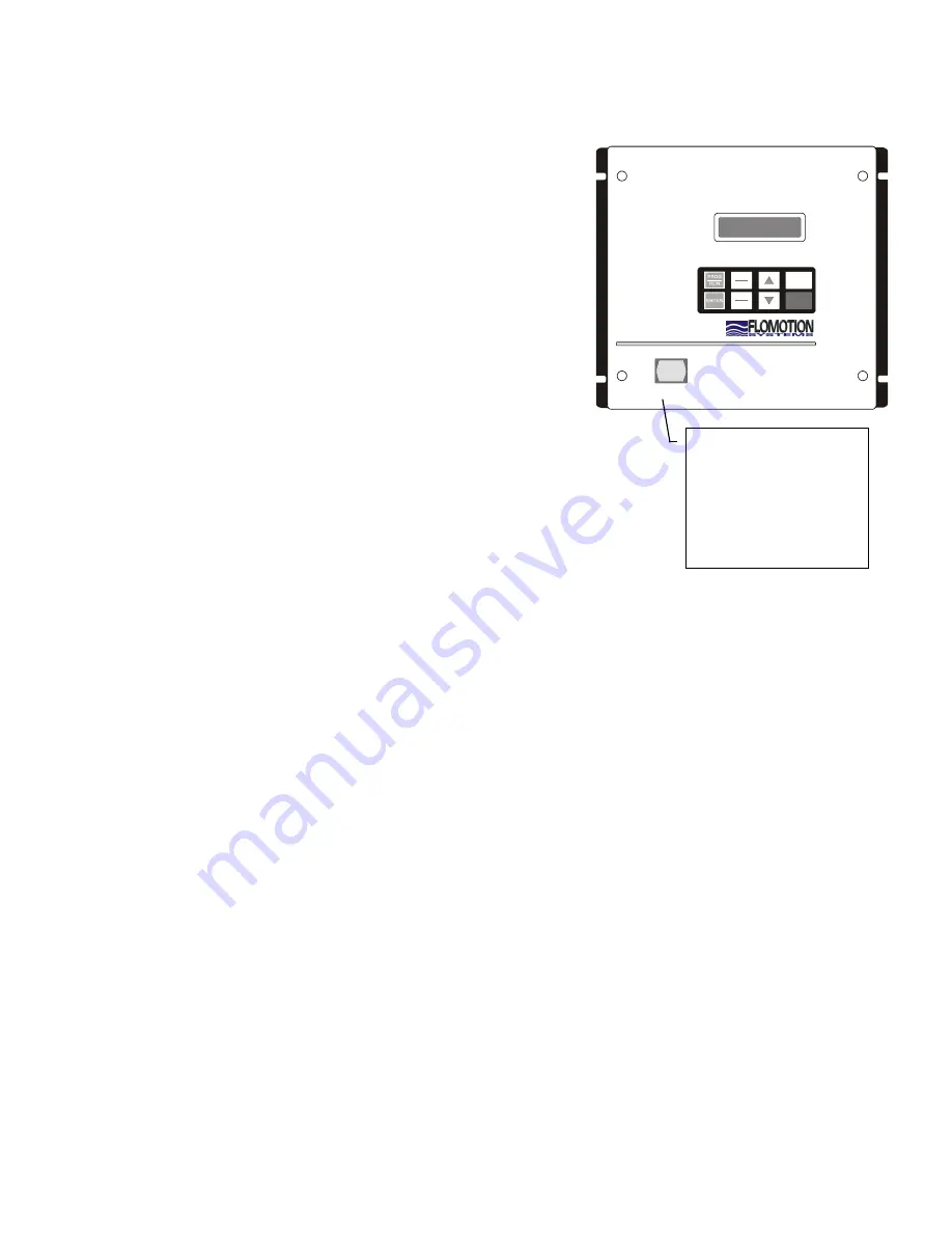
AUTO
START
STOP
MAN
LOCAL
REMOTE
Auto / Manual
Indicator
(LED On = AUTO)
&
Manual Motor
Start Pushbutton


