


is located on the left-hand storage cabinet, for-
ward of the cabin door. Additional lighting
controls are located in the individual seat pas-
senger control units (for reading and table
lights), master control panel and the lavatory
control panel (fluorescent and spotlights).
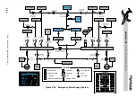
A main entryway control panel, as illustrated
in Figure 3-7 is installed at the forward side
of the entry door opening. There are six push-
push switches incorporated in the panel as-
sembly. They operate as follows:
COCKPIT
Provides remote ON/OFF
c o n t r o l f o r p i l o t ’s s i d e
overhead light (using right
hot bus power).
ENTRY
Provides ON/OFF control
for door entry light (using
right hot bus power).
CABIN LIGHT
Provides ON/VARIABLE/
OFF control for cabin over-
head fluorescent lights.
SPOT LIGHT
Provides ON/OFF control
for all spotlights in cabin.
Spotlights include reading
lights, table lights, cabin
entry light and lavatory
spotlights.
LAV LIGHT
Provides ON/VARIABLE/
OFF control for the lava-
tory overhead fluorescent
lights.
PYLON
Provides ON/OFF control
for optional lights on the
under side of each engine
pylon that illuminate the
tailcone baggage door area
and the single point refu-
e l i n g r e c e p t a c l e a r e a s
(using rear hot bus power).
A cabin lighting switch panel is also located
on the co-pilot’s side panel, aft of the circuit
breaker panel (Figure 3-7). These switches
c a n b e u s e d t o ove r r i d e a n d d i s a b l e t h e
switches on the main entryway control panel.
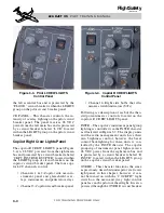
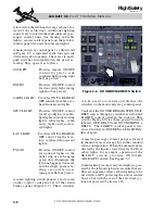
Control of the NO SMOKING/FASTEN SEAT
BELT sign is through a switch located on the
LIGHTS control panel in the cockpit. This
switch (Figure 3-6) is a three-position switch
labeled “OFF, BELTS and NO S
BELTS.” The LIGHTS control panel is dis-
cussed further in EXTERNAL LIGHTING,
this chapter.
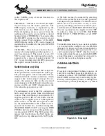
A master passenger control panel is located
in the mid-aft seat storage box in the standard
cabin configuration. When the menu item in-
dicated by the liquid-crystal display (LCD) is
cabin lights, for example, operation of the
S E L E C T s w i t c h p r o v i d e s O N / VA R I -
ABLE/OFF control. See Figure 3-7.
Cabin lighting (except entry/exit light) is pow-
ered by the left and right non-essential busses.
This arrangement allows cabin lighting to be
used with a GPU powering the non-essential
busses, but with the rest of the electrical sys-
tem not powered (batteries off).
L E A R J E T 4 5
P I L O T T R A I N I N G M A N U A L
3-6
FOR TRAINING PURPOSES ONLY
FlightSafety
international
Figure 3-6. NO SMOKING/BELTS Switch