


DUAL GENERATOR FAILURE
Dual generator failure would become most ap-
parent with illumination of the red GEN FAIL
annunciator on the CWP and the accompany-
ing flashing Master Warning lights. Also the
CAS would display a red “L R GEN FAIL”
message. Generator failure can be verified by
n o t i n g z e r o l e f t a n d r i g h t a m p s o n t h e
E I C A S / M F D S U M RY o r E L E C s y s t e m
schematic display and OFF illuminated in each
generator switch.
The red “LR GEN FAIL” CAS will not illu-
minate during ground operations with both
generators OFF and either white “L/R ENG
SHUTDOWN” CAS illuminated. However,
the red “LR GEN FAIL” CAS will illuminate
in flight regardless of whether a “L or R ENG
SHUTDOWN” CAS is illuminated.
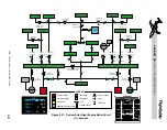
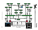
With a double generator failure in flight, main
airplane batteries and the emergency battery
powers the DC electrical systems. Figure 2-24
illustrates how both main busses, both main
avionics busses and both non-essential busses
have been automatically depowered to imme-
diately shed the electrical load. Also, the right
isolation contactor automatically opens leav-
ing the emergency battery to power the emer-
gency battery bus. The bus tie remains open,
so the left battery will power the left essential
bus and left essential avionics bus, and the
right battery will power the right essential bus
and the right essential avionics bus. The AFM
procedure for L and R GEN FAIL is to turn off
the avionics master switches which will also
cause the loss of the left and right essential
avionics busses.
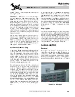
Indications on the electrical control panel with
a dual generator failure would be OFF cap-
tions on the left and right MAIN bus switches,
NON-ESS bus switches and GEN switches.
Also, the EMER captions on the emergency bat-
tery switch would be illuminated indicating the
emergency battery is powering the emergency
battery bus. The OFF captions in the L and R
AV MSTR will also be illuminated when the
avionics master switches are selected off.
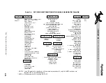
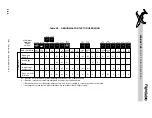
Table 2-4 shows what components and sub-sys-
tems will be available under a dual generator
failure situation. In addition, both essential
avionics, both main busses and both main
avionic busses are available by manual selec-
tion if desired; however, this will significantly
reduce the main battery time duration.
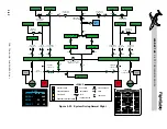
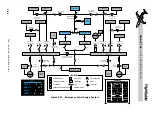
Figure 2-25 illustrates the electrical system in
the event of a dual generator failure followed
by main battery failure, but with the EMER
BATT still powering the EMER BATT BUS.
Table 2-5 illustrates the condition of the DC
electrical system contactors during some pos-
sible abnormal conditions. The table also shows
which contactors will be operated manually.
L E A R J E T 4 5
P I L O T T R A I N I N G M A N U A L
2-36
FOR TRAINING PURPOSES ONLY
FlightSafety
international