


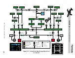
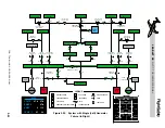


Figure 2-21 illustrates the status of the con-
tactors and busses after engine start with one
engine-driven generator on-line. The essential
bus contactors have closed and the left isola-
tion contactor opened. Also, the contactors
to the non-essential busses have closed. The
bus-tie contactor remains closed at this point
so that both generator busses are powered by
the single generator.
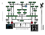
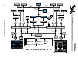
Figure 2-22 illustrates the electrical system
contactor and bus status for normal flight con-
ditions. After the second engine-driven gen-
erator is brought on-line, the bus-tie opens
and will remain open as long as both genera-
tors remain on-line and the bus tie is not man-
ually selected closed.
AC POWER
GENERAL
As part of the anti-ice protection system, left
and right windshield heaters are powered by
two, left and right engine-driven alternators.
The alternators are mounted to the front of
the engine accessory drive box, next to the
starter/generator, and operate from 6,000 to
12,000 rpm (Figure 2-7).
The alternators supply 200 VAC, 200-400 Hz
at a maximum of 5 KVA single phase output.
The alternator output is controlled by a sepa-
rate control unit that contains the monitor cir-
c u i t r y f o r t h e w i n d s h i e l d . T h e r e a r e n o
provisions for directly monitoring alternator
output on the EICAS displays, but loss of AC
power from an alternator would be detected by
failure of windshield anti-ice.
The output of the alternators is only used by
the windshield anti-ice.
L E A R J E T 4 5
P I L O T T R A I N I N G M A N U A L
2-27
FOR TRAINING PURPOSES ONLY
FlightSafety
international