


after the switch is turned on while on the
ground and for 1 minute in flight. The red
“WING OVHT” or red “STAB OVHT” CAS
message will be displayed if the correspond-
ing surface is in excess of the temperatures
shown in Figure 10-6.
The controller also monitors sensor inputs for
validity. If a wing sensor has failed or the high
or low temperature sensor input is invalid, a
“WING TMP FAULT” CAS message will be
displayed. If a stabilizer sensor has failed or
the high or low temperature sensor input is in-
valid, a “STAB TMP FAULT” CAS message
will be displayed. Wing and stabilizer anti-ice
should still function normally with either fault
message displayed.
The wing/stab anti-ice system is tested by ro-
tating the airplane system test selector knob
to the “ANTI-ICE” position, and depressing
the push-to-test button. This test checks the cir-
cuits that supply the discreet inputs to the
ECS controller. A white advisory message,
“WG/STAB HT OK” is displayed on the CAS
for a satisfactory test. The red WING OVHT
and STAB OVHT annunciators on the CWP
also illuminate with this test.
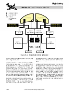
Wing/Stab Anti-Ice Leak Detector
Ducting for the wing and stabilizer anti-ice
bleed-air is monitored by a leak detection sys-
tem. It is a series of interconnected heat de-
tection elements connected to a leak detector
unit. The system works the same as the engine
fire detection system. The heat detecting ele-
ments are routed beside the anti-ice ducting
from the wing leading edge, aft, and up through
the vertical stabilizer to the leading edge of the
horizontal stabilizer (Figure 10-6). A bleed-
air leak or overtemperature (approximately
255° F) anywhere along the heat detection el-
ement causes the red “WING/STAB LEAK”
message to be displayed on the CAS and the
WING/STAB LEAK annunciator on the CWP
to illuminate. These warnings remain on until
the temperature decreases. The flight manual
10-11
FOR TRAINING PURPOSES ONLY
L E A R J E T 4 5
P I L O T T R A I N I N G M A N U A L
FlightSafety
international
R REV
UNSAFE
R OIL
PRESS
LOW
R ENG
PYLON
OVHT
R FUEL
PRESS
LOW
ENTRY
DOOR
GEN FAIL
R BLEED
AIR
LEAK
R BATT
OVHT
STAB
OVHT
EMER
BATT
WING/
STAB
LEAK
L BATT
OVHT
WING
OVHT
GEAR
L BLEED
AIR
LEAK
NORMAL
BRAKES
FAIL
L ENG
PYLON
OVHT
L FUEL
PRESS
LOW
L REV
UNSAFE
L OIL
PRESS
LOW
STAB
OVHT
WING/
STAB
LEAK
WING
OVHT
WING/STAB LEAK
STAB OVHT
WING OVHT
STAB TEMP LOW
WING TEMP LOW
STAB TMP FAULT
WING/STAB HT OK
WING TMP FAULT
END
N1
ITT
SAT C
CAS
FUEL
FLT
ECS
HYD
ELEC
SUMRY
L
F
1000
R
1750
FLAPS
20
6.5
PITCH TRIM
LBS
FUEL
4450
-15
50.0
76
60
984
50.0
80
60
1002
N2
OIL PSI
OIL C
FF PPH
550
550
75.0
75.0
1700
ELECT
VOLTS
EMER-V
AMPS
TEMP C
28.5
28.0
28.0
200
300
30
50
HYD/ECS
MAIN
B-ACUM
OXY C
OXY PSI
3000
2000
+10
1800
FLT
SPLR
PIT
AIL
RUD
0
0
R 3
L 2
Honeywell
Honeywell
WING/STAB LEAK
STAB OVHT
WING OVHT
STAB TEMP LOW
WING TEMP LOW
STAB TMP FAULT
WING/STAB HT OK
WING TMP FAULT
END
R REV
UNSAFE
R OIL
PRESS
LOW
R ENG
PYLON
OVHT
R FUEL
PRESS
LOW
ENTRY
DOOR
GEN FAIL
R BLEED
AIR
LEAK
R BATT
OVHT
STAB
OVHT
EMER
BATT
WING/
STAB
LEAK
L BATT
OVHT
WING
OVHT
GEAR
L BLEED
AIR
LEAK
NORMAL
BRAKES
FAIL
L ENG
PYLON
OVHT
L FUEL
PRESS
LOW
L REV
UNSAFE
L OIL
PRESS
LOW
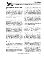
Figure 10-7. Wing/Stab Anti-Ice System Warnings on CWP and EICAS