WINDSHIELD ANTI-ICE AND
DEFOG SYSTEM
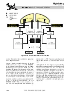
The windshield anti-ice system uses power
from two dedicated engine-driven alternators
to heat integral film elements contained within
the outer layers of the windshield for external
anti-icing and internal defog.
The system consists of a dual channel wind-
shield controller, two engine mounted alter-
nators, two external relays, two heating
elements, two normal and two overheat sen-
sors, anti-ice control panel switches, and elec-
trical circuitry in the aft power distribution
panels. See Figure 10-5.
The two windshield anti-ice sections (pilot
and copilot) are independently controlled and
are powered through the respective left and
right engine-driven alternators mounted on
the front right side of the engine accessory gear
boxes. Each of the 5 KVA alternators produce
200 VAC, between 200 and 400 Hz, depend-
ing upon the engine speed, to heat the wind-
shield anti-ice and defog elements. The
alternators supply power to the same-side
windshield only. If one alternator or one en-
gine fails, the corresponding side windshield
anti-ice/defog will be inoperative.
The windshield is a layered polycarbonate
and urethane design with a glass outer layer.
The underside of the glass is coated with a form
of tin oxide that conducts electricity. The heat-
ing element is the tin oxide layer that is heated
via AC electricity. Each windshield half con-
tains normal and overtemperature sensors
imbedded in the upper forward section. The
sensors send temperature information to the
windshield controller.
The two channels of the controller are sepa-
rated electrically and have separate power
sources. Each channel of the controller inde-
pendently regulates the output of the respec-
tive alternator through an external relay to
control the temperature of the on-side wind-
shield section. The controller also signals an
external relay (not shown in Figure 10-5) on
the affected side to disconnect power from
the heating element in the event of overheat-
ing of a windshield section. In addition, the
controller provides output signals to initiate
10-6
FOR TRAINING PURPOSES ONLY
L E A R J E T 4 5
P I L O T T R A I N I N G M A N U A L
FlightSafety
international
N1
ITT
END
50.0
76
50.0
80
N2
550
550
75.0
75.0
Honeywell
NAC
NAC
L R NAC HT
L R NAC HT FAIL ON
Figure 10-4. Engine Anti-Ice Annunciations on EICAS


