


High-Pressure (HP) Turbine
The HP turbine is a single-stage, axial-flow
turbine and is located so that it receives the ini-
tial high temperature gas flow from the com-
bustion chamber. The HP turbine is rigidly
connected to the HP compressor, and together
they form the HP rotating group, which is also
referred to as the HP spool.
The HP turbine extracts sufficient energy from
the combustion gases to drive the HP com-
pressor and the accessory section. The HP ro-
tating group rpm is referred to as N2, or turbine
speed.
Low-Pressure (LP) Turbine
The low-pressure turbine consists of three
axial-flow turbine discs rigidly connected to
the four-stage LP compressor by the LP rotor
shaft which extends through the center of the
HP spool. The LP rotor shaft is also extended
forward to drive the planetary reduction gears.
The LP turbine extracts sufficient energy from
the expanding combustion gases to drive the
LP compressor directly and, in addition, drives
the fan through the planetary reduction gear
system. The fan, the LP compressor, and the
LP turbine are directly linked and form the LP
rotating group. The LP rotating group rpm is
referred to as the N1, or fan speed.
Located between the HP and the LP turbines
are ten thermocouples that extend into the gas
path and report the interstage turbine tem-
perature (ITT).
The combustion gases are then exhausted
through the exhaust duct.
EXHAUST SECTION
The resulting thrust created by the combustion
air passing through the exhaust section adds
to the thrust generated by the inlet fan, pass-
ing through the bypass air duct, to produce the
total propulsion force.
The exhaust section consists of the bypass air
duct, the thrust and exhaust nozzle, the inter-
stage transition duct and the thrust reverser.
ACCESSORY SECTION
The accessory section consists of a transfer
gearbox and an accessory drive gearbox lo-
cated on the lower forward area of the engine.
The transfer gearbox houses the N2 speed sen-
sor and is driven by the tower shaft and bevel
gear from the HP spool. A horizontal drive
shaft interconnects the transfer gearbox to the
accessory drive gearbox to drive the follow-
ing accessories:
Located on the rear of the accessory drive and
described within this chapter:
• Oil Pump
• Fuel Pump
• Fuel Control Unit (FCU)
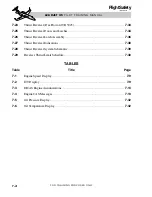
Located on the front of the accessory drive
(Figure 7-3):
• DC Starter/Generator
• AC Alternator
• Hydraulic Pump
• Motive Flow Fuel Pump
L E A R J E T 4 5
P I L O T T R A I N I N G M A N U A L
7-5
FOR TRAINING PURPOSES ONLY
FlightSafety
international
DEEC
ALTERNATOR
STARTER/GENERATOR
HYDRAULIC PUMP
MOTIVE FLOW
FUEL PUMP
Figure 7-3. Accessory Drive Components