28
ZAPEX 3502 en
Operating instructions 10/2017
6.7.1
Axial misalignment
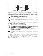
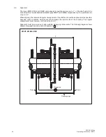
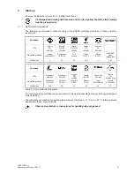
Axial misalignment ΔKa (figure 6.4) of the coupling parts relative to one another is possible within the
"permissible error" for dimension "S" (see section 1).
6.7.2
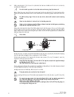
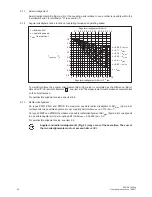
Angular misalignment as a function of operating torque and operating speed
0.2
T
operation
/ T
N
0.1 0.2 0.3 0.4 0.5 0.6 0.7 0.8 0.9 1.0
2
4
6
8
10
12
14
17.5
0
0.3
0.4
0.5
0.6
0.7
0.8
0.9
1.0
Angular misalignment ΔKw in °
Angular misalignment ΔKw in 10
3
rad
n = 0.063
n
max.
n = 0.1
n
max.
n = 0.16
n
max.
n = 0.25
n
max.
n = 0.4
n
max.
n = n
max.
n = 0.63
n
max.
T
N
from section 1
n = operating speed
n
max.
from section 1
16
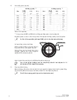
To simplify matters, the angular misalignment ΔKw (figure 6.5) is calculated as the difference (ΔS) of
dimension "S" (for point of alignment
A
, see item 6.6). The measurement must be taken at several points
on the circumference.
For permissible alignment values, see item 6.8.
6.7.3
Radial misalignment
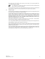
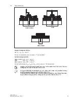
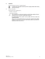
On types ZWB, ZWH and ZWHD the maximum possible radial misalignment ΔKr
max.
(figure 6.6)
corresponds to a possible angular error per coupling half of ΔKw
max.
= 0.0175 rad = 1°.
On types ZWBT and ZWBG the maximum possible radial misalignment ΔKr
max.
(figure 6.6) corresponds
to a possible angular error per coupling half of ΔKw
max.
= 0.00525 rad = 0.3°.
For permissible alignment value, see item 6.8.
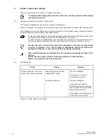
Angular and radial misalignments (Fig. 6.7) may occur at the same time. The sum of
the two misalignments must not exceed
Δ
Kw or
Δ
Kr.
Summary of Contents for Zapex ZWB
Page 2: ......

