


Assembling
5.2 Assembling the coupling
M3302-01en
Edition 09/2022
35
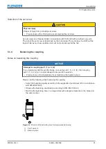
5.2.3
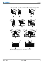
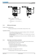
Mounting rubber disk element 5 (5) on the shaft for type EST using a
TAPER clamping bush with a parallel key
5.2 Assembling the coupling
DANGER
Danger of explosion
Improper operation of the coupling can lead to an explosion in potentially explosive atmo-
spheres.
•
Make sure that a parallel key has been inserted in the shaft.
•
Apply a small quantity of liquid screw locking agent (e.g. Loctite 243, medium strength)
to the threads of the screws for the TAPER clamping bush (105).
Procedure
1. Clean the bores, the shaft ends and the TAPER clamping bush (105).
The large front face of the TAPER clamping bush (105) has two axis-parallel half blind
holes up to size 3030 and three in the case of size 3535 and larger. The rubber disk ele-
ment 5 (5) has half threaded holes in the same angular position.
2. Insert the TAPER clamping bush (105) in the rubber disk element 5 (5).
3. Line up the half blind holes of the TAPER clamping bush (105) with the half threaded
holes of the rubber disk element (5).
4. Apply a small quantity of liquid screw locking agent (e.g. Loctite 243 medium strength) to
the screws of the TAPER clamping bush.
5. Insert the screws for the TAPER clamping bush (105) into the blind hole/threaded hole
combination and tighten them slightly.
6. Position the rubber disk element 5 (5) together with the TAPER clamping bush (105) on
the shaft. The shaft must not be set back from the inner side of the hub.
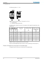
For motor and generator connection dimensions according to the standard DIN 6281,
take into account the clearances LX and T (see Section Permissible deviations for the
clearances A, S, LG, T, LX (Page 73)) and the coupling dimension LG (see Section Di-
mension drawing of type EST (Page 72)).
7. Gradually tighten the screws for the TAPER clamping bush (105) in sequence up to the
specified tightening torque T
an (see Table A-27 Tightening torques and widths A/F for
the bolts for the TAPER clamping bushes (105) (Page 77)).
As the screws are tightened, the hub is drawn against the TAPER clamping bush (105)
and the bush thus pressed onto the shaft.
8. Fill any unused bores of the TAPER clamping bush (105) with a suitable grease to pre-
vent the ingress of dirt.
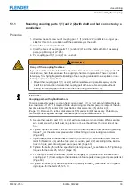
5.2.4
Mounting coupling part 3 (3) with a flanged connection
5.2 Assembling the coupling
The coupling part 3 (3) is available in a one-part and a two-part version.
The procedure for mounting the coupling parts 3 (3) varies depending on the version.
Summary of Contents for ELPEX-S
Page 6: ...Table of contents 6 Edition 09 2022 M3302 01en ...
Page 8: ...List of tables 8 Edition 09 2022 M3302 01en ...
Page 10: ...List of figures 10 Edition 09 2022 M3302 01en ...
Page 14: ...Introduction 1 4 Copyright 14 Edition 09 2022 M3302 01en ...
Page 22: ...Description 22 Edition 09 2022 M3302 01en Structure ...
Page 38: ...Assembling 5 3 Aligning the coupling 38 Edition 09 2022 M3302 01en ...
Page 40: ...Commissioning 40 Edition 09 2022 M3302 01en ...
Page 46: ...Operation 7 2 Fault causes and correction 46 Edition 09 2022 M3302 01en ...
Page 56: ...Service and support 9 1 Contact 56 Edition 09 2022 M3302 01en ...