
Assembling
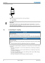
5.2 Assembling the coupling
34
Edition 09/2022
M3302-01en
11.If, for the types ESNW and ESDW, you have removed the coupling part 3 (3), screw the
flange (101) together with the face end of coupling part 3 (3) according to the illustration
in Spare parts drawing and spare parts list (Page 60).
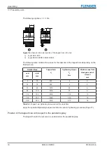
12.Tighten the bolts (31) with the specified tightening torque T
A
torques for the bolts 25, 125, 31 (Page 76)).
5.2.2
Mounting coupling parts 1 (1) and 2 (2) with shaft and hub connected by a
pressurised oil interference fit
5.2 Assembling the coupling
Procedure
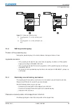
1. Dismantle the rubber disk element 5 (5) and/or 6 (6). For further information, refer to
section Replacing wearing parts (Page 48).
2. Remove the screw plugs (101) and/or (201) from the coupling parts 1 (1) and/or 2 (2).
3. Clean, degrease, de-oil and dry the bores and shaft ends.
4. Clean and dry the oil channels and the oil circulation grooves.
5. Protect adjacent components against damage and heating to temperatures above 80 °C.
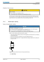
6. Heat up the coupling parts 1 (1) and/or 2 (2) to the temperature specified in the dimen-
sion drawing.
Make sure that no dirt or contaminants can soil the bores again during the heating pro-
cess.
7. Mount the coupling parts 1 (1) and/or 2 (2) quickly on the shaft according to the instruc-
tions in the dimension drawing.
8. Secure the coupling parts to stop them from moving until they have cooled down.
9. Allow the coupling parts to cool down to the ambient temperature.
10.Use an end plate to secure the coupling parts that have a non-self-locking, tapered pres-
surised oil interference fit.
11.In order to protect the oil channels of the coupling parts 1 (1) and/or 2 (2) against corro-
sion, fill them with a suitable pressurised oil and seal the oil channels with the screw
plugs (101) and/or (201).
12.Screw the rubber disk element 5 (5) and/or 6 (6) together with the face end of coupling
part 2 (2) according to the illustrations in Spare parts drawing and spare parts list
(Page 60).
13.Tighten the bolts (25) with the specified tightening torque T
A
torques for the bolts 25, 125, 31 (Page 76)).
14.For the types ESNW and ESDW, screw the flange (101) together with the face end of
coupling part 1 (1) according to the illustrations in Spare parts drawing and spare parts
list (Page 60).
15.Tighten the bolts (125) with the specified tightening torque T
A
(see Table A-25 Tighten-
ing torques for the bolts 25, 125, 31 (Page 76)).
16.If, for the types ESNW and ESDW, you have removed the coupling part 3 (3), screw the
flange (101) together with the face end of coupling part 3 (3) according to the illustration
in Spare parts drawing and spare parts list (Page 60).
17.Tighten the bolts (31) with the specified tightening torque T
A
Summary of Contents for ELPEX-S
Page 6: ...Table of contents 6 Edition 09 2022 M3302 01en ...
Page 8: ...List of tables 8 Edition 09 2022 M3302 01en ...
Page 10: ...List of figures 10 Edition 09 2022 M3302 01en ...
Page 14: ...Introduction 1 4 Copyright 14 Edition 09 2022 M3302 01en ...
Page 22: ...Description 22 Edition 09 2022 M3302 01en Structure ...
Page 38: ...Assembling 5 3 Aligning the coupling 38 Edition 09 2022 M3302 01en ...
Page 40: ...Commissioning 40 Edition 09 2022 M3302 01en ...
Page 46: ...Operation 7 2 Fault causes and correction 46 Edition 09 2022 M3302 01en ...
Page 56: ...Service and support 9 1 Contact 56 Edition 09 2022 M3302 01en ...