Fleece Duramax PowerFlo LB7 Installation Instructions Manual Download Page 1


SUBJECT:


2001 

 2004 LB7 Duramax PowerFlo Lift Pump 


FPE-2021-58 
July, 2021 
 

FITMENT: 

2001

2004 LB7 Duramax equipped Chevy/GMC trucks


KIT P/N: 

FPE-34809 

EST. INST. TIME: 

3 hours 

TOOLS 

REQ’D: 


1/2

” and

 3/8

” fuel disconnect tools

 (included),


15mm deep socket and ratchet,


8 mm socket and 

ratchet,


hammer, chisel or drift. 
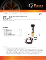


KIT CONTENTS: 


Item 

Description 

Qty 

PowerFlo lift pump 

Chassis harness 

Tank flange seal 

Level sender float 

3/8” Fuel line disconnect tool


1/2" Fuel line disconnect tool 


WARNINGS: 


Fuel system, including fuel tank, fuel supply, and fuel return lines must be clean before installation. 


Use of this product may void or nullify the vehicle’s factory warranty.


The purchaser and end user releases, indemnifies, discharges, and holds harmless Fleece Performance Engineering, Inc. 
from any and all claims, damages, causes of action, injuries, or expenses resulting from or relating to the use or installation 
of this product that is in violation of the terms and conditions on this page, the product disclaimer, and/or the product 
installation instructions. Fleece Performance Engineering, Inc. will not be liable for any direct, indirect, consequential, 
exemplary, punitive, statutory, or incidental damages or fines cause by the use or installation of this product. 

Summary of Contents for Duramax PowerFlo LB7

Page 1: ...uel supply and fuel return lines must be clean before installation Use of this product may void or nullify the vehicle s factory warranty The purchaser and end user releases indemnifies discharges and...

Page 2: ...er neck and remove the filler neck from the tank STEP 4 Remove the fuel lines at the front of the tank and at the fuel cooler with a 3 8 and 1 2 fuel line disconnect tool NOTE Thoroughly clean the fue...

Page 3: ...tank when the sending unit is removed STEP 7 Remove the fuel lines at the sending unit with the quick disconnect tools STEP 8 Using a hammer and a chisel or punch remove the locking ring by tapping t...

Page 4: ...talling the fuel level float arm Install the fuel level float arm onto the lift pump by gently clipping the arm into the fuel level sensor STEP 13 Install the PowerFlo pump assembly into the tank and...

Page 5: ...all the fuel tank hangers reconnect the fuel lines at the front of the tank by the fuel cooler and install the vent tube and tighten the hose clamp STEP 17 Complete the wiring harness installation in...

Page 6: ...Wire To Battery positive terminal Red Wire To Switched Ignition in Fuse Block Black Connectors To OEM harness and PowerFlo lift pump Relay Provides switched 12v power to the PowerFlo pump To OEM harne...

Page 7: ...the fuse panel into the second fuse tap terminal We recommend using the fuse tap in location IGN E if available Insert the original fuse from the fuse block into the relay tap below the 5A fuse that...

Reviews: