DISCONNECT POWER BEFORE REMOVING THE GUARDS FOR ANY REASON
1
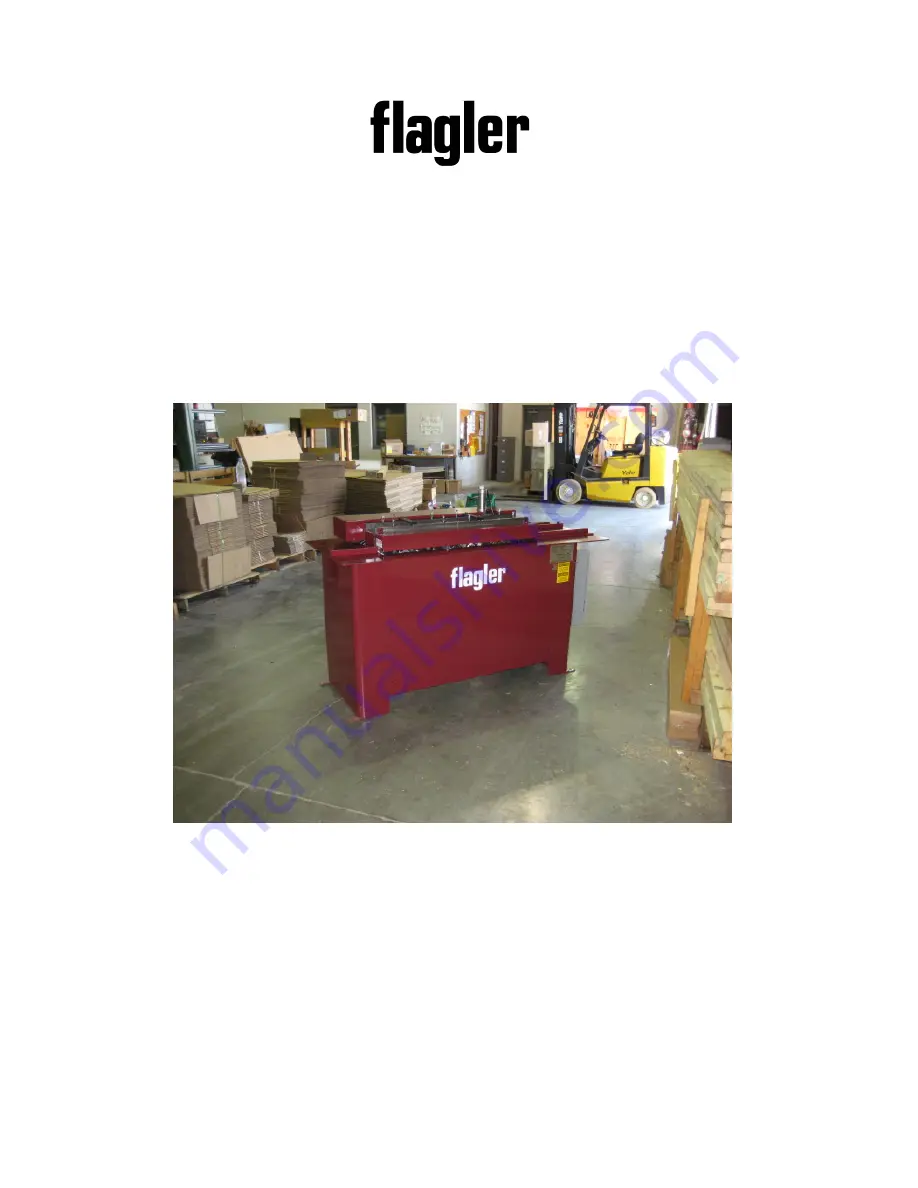
General Operating Instructions
Flagler Model H-2 ½-10 Equipped with Drive Turn Hemming Rolls
The
Flagler
Corporation
56513
Precision
Dr.
Chesterfield,
MI
48051
USA
www.flaglercorp.com
(586)
749-6300
Fax
(586)
749-6363
[email protected]


