


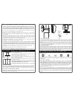


INSTALLING MOUNTING BRACKET (See diag. 1 on following page)
Align the center of the installation bracket with the center of the cooking surface (use of plumb bob
recommend). Place the flat/horizontal surface of the mounting bracket 8~1/2” (216mm) above the
installation height (diag.1). Ensuring the mounting bracket is level, mark and drill the holes in
the wall. Use the screws and plugs provided to attach bracket.
I N S TA L L I N G C H I M N E Y B R A C K E T
C u t c o r n i c e t o s u i t t h e c h i m n e y c o v e r. A l i g n t h e c e n t e r o f t h e c h i m n e y b r a c k e t
w i t h t h e c e n t e r o f t h e c o o k i n g s u r f a c e . M a r k a n d d r i l l t h e h o l e s i n t h e w a l l a n d
c e i l i n g . U s e t h e m o u n t i n g s c r e w s a n d a n c h o r s p r o v i d e d .
c) Warning - Remove transport tape from the lights and the filters before use.
d) Sufficient air is needed to provide proper combustion and exhausting of gases through the flue
(chimney) of fuel burning equipment to prevent back draughting. Follow the heating equipment
manufacturer’s guideline and safety standards such as those published by the National Fire
Protection Association (NFPA), and the American Society for Heating, Refrigeration and Air
Conditioning Engineers (ASHRAE), and the local code authorities.
e) When cutting or drilling into wall or ceiling, do not damage electrical wiring and other hidden
utilities.
f) This appliance
must
always be vented to the outdoors.
g) The canopy is heavy: overall weight 65 lbs (29kg). Please ensure adequate care when installing the
canopy to prevent personal injury. The canopy must be installed onto a solid wall or solid studs.
h) Before servicing or cleaning unit, switch power off at the service panel and lock the service
disconnection means to prevent power from being switched on accidentally. When the service
disconnection means cannot be locked, securely fasten a prominent warning device, such as a tag,
to the service panel.
i) WARNING - TO REDUCE THE RISK OF FIRE, USE ONLY METAL DUCTWORK.
WARNING - GROUNDING INSTRUCTIONS
a) This appliance must be grounded. In the event of an electrical short circuit, grounding reduces
the risk of electrical shock by providing an escape wire for the electric current. This appliance
is equipped with a cord having a grounding wire with a grounding plug. To provide protection
against electric shock the plug must only be plugged into an outlet that is properly installed and
grounded.
b) WARNING - Improper grounding can result in a risk of electric shock.
c) Appliance to be connected to a 15/20A circuit breaker.
d) Consult a qualified electrician if the grounding instructions are not completely understood, or if
doubt exists as to whether the appliance is properly grounded.
e) Do not use an extension cord. If the power supply cord is too short, have a qualified electrician
install an outlet near the appliance.
NOTE: Stainless steel and iridium is very easily damaged during
installation if abraided or knocked by tools.
Read the instructions before starting the assembly. Remove the filters to
allow access to wall mounting holes.
The unit is designed for ceilings 7’ 6” to 8’ 10” (2290 to 2690mm) high.
The chimney is telescopic and is designed to adjust between 25~1/2” and
35~1/2” (650 to 900mm).
Ascertain the desired installation height of the canopy. NOTE: Installation
height ranges from 24” to 30” (610 to 760mm).
DUCTING: Ducting accessories are not supplied. The air outlet from
the adaptor (attached to the motor) is 7” (178mm). 7” (178mm) ducting
will require a clearance hole of 7~5/16” (186mm) in the ceiling.
Ceiling height
7’6” to 8’10”
(2290 to 2690)
Installation height
24” to 30”
(610 to 760)
Cooking surface
36” (914)
I N S T A L L A T I O N I N S T R U C T I O N S
Disconnect the power to the rangehood. Using a small bladed screwdriver prise off the light cover. If
the bulb is hot use a cloth to remove the bulb. Replace with a new bulb using a cloth. Do not
touch the new bulb with your fingers as the grease from your fingers will crack the bulb when it is
switched on. “Snap” the cover back in place. A halogen bulb 12Volt/20Watt is required.
For other accessories, parts or service, please contact your local supplier (Refer to the Warranty
Certificate).
CLEANING INSTRUCTIONS
Care and attention should always be taken when cooking with oils, alcohol, etc, which give off
flammable vapours. Pre-used oil is especially dangerous in this respect. Do not use an
uncovered electrical grill. Particular care must be taken with grease filters which must be
periodically cleaned, at least every two months. Remove the grease filters and wash them
either by hand or in the dishwasher using mild detergent. Use lukewarm water and mild
detergent to clean stainless steel/iridium components. In high humidity and coastal environments,
cleaning should be carried out frequently. CAUTION: Never use abrasive or oil based liquid cleaners.
INSTALLING THE CHIMNEY
A rubber extrusion has been provided to hide any irregularities between the chimney and the
canopy, it is fitted by simply pushing it over the bottom visible edges of the chimney.
This steel edge may be sharp so care must be taken to avoid damage to fingers. If
desired the extrusion may be omitted from the assembly.
Remove the protective plastic film from the chimney. Prior to mounting, determine the height
required on the chimney. The height can be adjusted by changing the screw on the
back lip (diag.2). Do not tighten the screws because the chimney needs to slide up when
installing the canopy. Mount the chimney to the ceiling bracket using the screws provided.
INSTALLING THE CANOPY
Ensure the filters are removed from the canopy. Hang the canopy onto the installation bracket.
Align the canopy so it is central to the cooking surface and lines up with the chimney cover. Mark
out the position of the two safety screw holes located on the back panel. Remove the canopy, drill
the safety screw holes and fit wall plugs. Refit the canopy to the wall and secure using the
appropriate mounting screws (diag.3). Remove the protective plastic film from the canopy and
filters. Refit the filters to the canopy.
LIGHT REPLACEMENT (See diag. 4)
diag.2
diag.3
8~1/2”
diag.1
”2/
1~
8
th
gi
eh
noi
tall
ats
ni
cooking surface
BULB
diag.4
O P E R A T I O N I N S T R U C T I O N S
CONTROL PANEL
Delay switch - Fan will remain on at low, mid or high speed for 5 minutes before switching off
automatically.
I
I I
I I I
Fan On/Off
Mid Speed
High Speed Delay Switch
Light On/Off
I