


321144
71
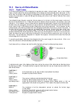
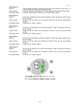
Example:
Add up the number corresponding to each LED that is on:
0.5 + 4 + 8 + 32 = 44.5
Subtract
40
from the result
44.5 - 40 = 4.5
o
C
Hence the temperature is
4.5
o
C.
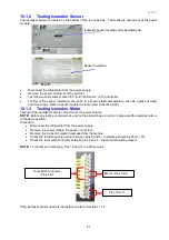
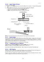
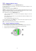
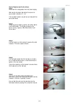
10.2.4 Input / Output Status
The Input/Output Status menu displays what devices (e.g. light, PC door, FC door, compressor, etc) are
currently running or turned on.
To enter the menu, the steps are:
1a.
Press and hold the
MODE
button (a short beep will sound).
1b.
Whilst still holding the
MODE
button, briefly press the
TEMPERATURE
UP
button (a short beep will
sound). This enters diagnostic mode.
Steps 1a and 1b need to be completed within 8 seconds.
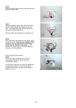
2.
Press the
TEMPERATURE UP
button 3 times.
The respective LED turns on when a device is running, as shown below.
3.
Return to normal operation by pressing the
MODE
button.
Upper door open
Lower door open
PC fan on
Low ambient heater on
Light on
FC fan on
Defrost heater on
Compressor on
Summary of Contents for 635 Active Smart
Page 1: ...321144 Service Manual 635 680 790 900 Active Smart Refrigerator Freezer R134a R600a Systems...
Page 2: ...321144 2...
Page 96: ...321144 96 Photo 12 22 5...
Page 100: ...321144 100 Diagram 12 25...
Page 108: ...321144 108 13 11 Embraco Compressor Fitted With External Overload Diagram 13 11...
Page 114: ...321144 114 14 2 Non Ice Water Models Wiring Diagram...
Page 116: ...321144 116 14 4 Ice Water Models Wiring Diagram...
Page 117: ...321144 117 14 5 900 Models Power Control Module Wiring Connections Reciprocating Compressor...
Page 118: ...321144 118 14 6 900 Models Wiring Diagram Reciprocating Compressor...
Page 119: ...321144 119 14 7 900 Models Power Control Module Wiring Connections VC Compressor...
Page 120: ...321144 120 14 8 900 Models Wiring Diagram VC Compressor...
Page 121: ...321144 121 14 9 B Model Wiring Route Diagram 14 9...
Page 122: ...321144 122 14 10 T Model Wiring Route Diagram 14 10...
Page 145: ......


