


321144
19
4
THEORY OF OPERATION
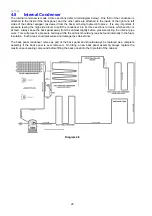
4.1
Terms
CABINET WRAPPER
Pre-painted steel.
LINER
A one-piece vacuum formed ABS liner with a plug-in divider
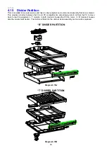
DIVIDER PARTITION
Injected moulding of HIPS, with two outer injected moulded housings, and an insulated ducted moulded
polystyrene inner core.
FAN MOTORS
DC 12 volt brushless variable speed fan motors for air circulation in both the FC and PC compartments.
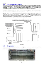
EVAPORATOR
Aluminium fin on tube type mounted vertically on the back wall of the FC.
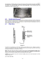
SUCTION and CAPILLARY LINE
Foamed into the back of the cabinet with all joints of the evaporator having been joined by induction brazing
in the FC.
POWER/CONTROL MODULE
Contains the microprocessor that controls all functions of the refrigerator and gathers data from the sensors.
This module also contains support circuitry to switch the various outputs.
DISPLAY MODULE
Using signals from the power/control module, this module generates the LCD or LED display.
REED SENSORS
A reed switch encapsulated within a plastic housing, mounted on the cross and base rails behind a plastic
cover. A magnet housed just under the lower end cap of each door activates this sensor when the door is
closed.
TERMS
Within this manual the following terms are used:
PC = Provision compartment
FC = Freezer compartment
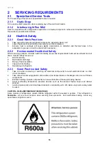
LOW AMBIENT HEATER
Two types are used. A PCB type used in the air duct of “T” models. A blanket wire type used in the divider
of “B” models.
Summary of Contents for 635 Active Smart
Page 1: ...321144 Service Manual 635 680 790 900 Active Smart Refrigerator Freezer R134a R600a Systems...
Page 2: ...321144 2...
Page 96: ...321144 96 Photo 12 22 5...
Page 100: ...321144 100 Diagram 12 25...
Page 108: ...321144 108 13 11 Embraco Compressor Fitted With External Overload Diagram 13 11...
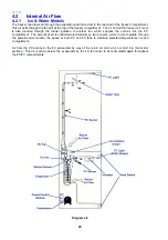
Page 114: ...321144 114 14 2 Non Ice Water Models Wiring Diagram...
Page 116: ...321144 116 14 4 Ice Water Models Wiring Diagram...
Page 117: ...321144 117 14 5 900 Models Power Control Module Wiring Connections Reciprocating Compressor...
Page 118: ...321144 118 14 6 900 Models Wiring Diagram Reciprocating Compressor...
Page 119: ...321144 119 14 7 900 Models Power Control Module Wiring Connections VC Compressor...
Page 120: ...321144 120 14 8 900 Models Wiring Diagram VC Compressor...
Page 121: ...321144 121 14 9 B Model Wiring Route Diagram 14 9...
Page 122: ...321144 122 14 10 T Model Wiring Route Diagram 14 10...
Page 145: ......


