Operating manual
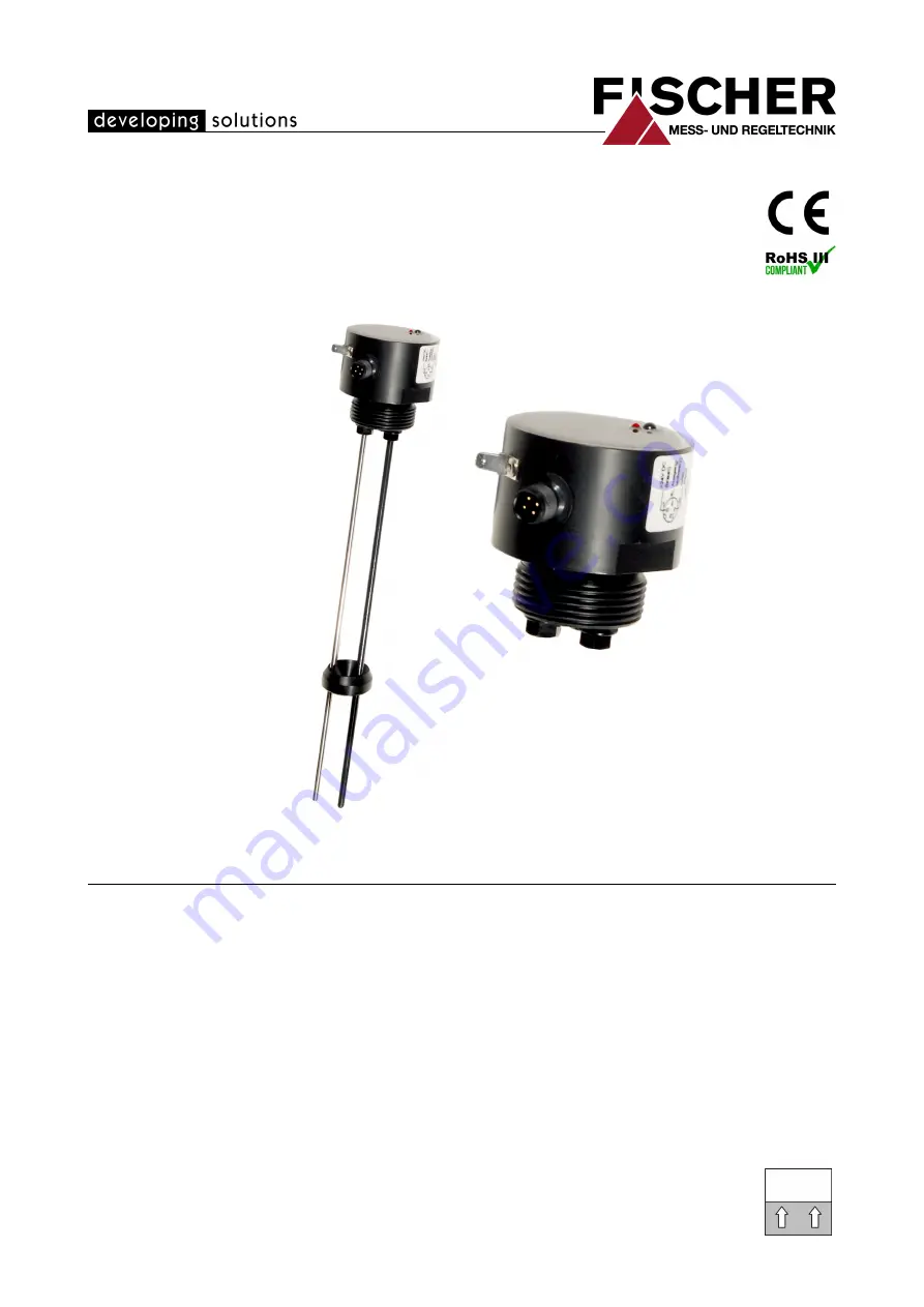
NC56
Capacitive filling level probe
09005621 • BA_EN_NC56 • Rev. ST4-A • 09/20
*09005621*
Page 1: ...Operating manual NC56 Capacitive filling level probe 09005621 BA_EN_NC56 Rev ST4 A 09 20 09005621...
Page 2: ...d using electronic systems or any other form print photocopy microfilm or another process without the written consent of the company FISCHER Mess und Regeltechnik GmbH Bad Salzuflen Reproduction for i...
Page 3: ...ram explanation 5 2 Product and functional description 6 2 1 Delivery scope 6 2 2 Intended use 6 2 3 Device versions 6 2 4 Function diagram 8 2 5 Design and mode of operation 8 3 Assembly 9 3 1 Genera...
Page 4: ...ess the work they have been assigned and recognize potential dangers by virtue of their specialized training their skills and experience and their knowledge of the pertinent standards 1 3 Risks due to...
Page 5: ...company is responsible for ensuring that all required mainten ance inspection and installation work is carried out by qualified specialized per sonnel 1 8 Pictogram explanation DANGER Type and source...
Page 6: ...of between 400 and 2000 mm can be measured The probe can be used regardless of the tank material metal plastic or concrete Please contact the manufacturer before using this device with dirty or aggre...
Page 7: ...on 7 Weight 2 3 1 Type plate The presented type plates serve to show an example of the information shown The data shown is purely fictive but does correspond to the actual conditions For more informat...
Page 8: ...operation An AC voltage signal is exerted onto two metal rods held at a defined distance to each other This means that the metal rods become a capacitor when dipped into fluids The capacitive values...
Page 9: ...ould be mounted at the highest point of the tank NOTICE See also the information about the calibration in the section Start up CA Initial capacitance probe exposed CE End capacitance probe covered Sho...
Page 10: ...ed length on the head end Remove 21 mm of the insulation shrink fit tubing on the head end It is best to remove the ECTFE coating with a belt sander Insert the electrodes to the noticeable stop point...
Page 11: ...Filling level probe Power Supply Output signal Input signal Sig Ub Ub Sig Ub Ub C DC AC DC Fig 8 3W connection The permitted operating voltage and the load impedance for the signal output are stated i...
Page 12: ...1 2 3 4 5 6 Data transfer Operation saving Fig 9 Calibration For the calibration you need an infrared remote control of type EU04 see ac cessories 1 Remove control EU04 2 Filling level probe 3 MIN but...
Page 13: ...vel is proportional to the filling volume in a cylindrical tank NOTICE This simple ratio no longer applies in the case of complex tank forms Depending on the tank geometry the filling level and tank c...
Page 14: ...The measuring device must be protected against impacts It should be transpor ted in the original packaging or a suitable transport container 5 3 Service All defective or faulty devices should be sent...
Page 15: ...Installation position vertical 6 2 Input variables Measuring range The measuring range lies between 400 mm and 2000 mm depending on the ordered probe length Other lengths available on request Input s...
Page 16: ...EC E13 72 245 95 54 2182 00 6 7 Construction design Electrical connection M12 connector 4 pin male Installation position vertical 6 7 1 Materials Materials of the parts that come into contact with the...
Page 17: ...8 4 Spacer every 500 mm Installation length 400 2000 mm M12 plug connector Spanner attachment SW55 Spacer every 500 mm Installation length 400 2000 mm 4 Probe with coated rod Protective tubing 60 SW7...
Page 18: ...5 Extinguishing foam agent ECTFE coating Bare 1 4404 S Cable probe Steel cable 1 4404 Steel cable 1 4404 6 Chemicals ECTFE coating ECTFE coating Casing material connection 2 Code no 0 Plastic casing w...
Page 19: ...no 2011 Version 7 1 Accessories Order no Designation No of poles Length 06401993 Connection cable with M12 connector 4 poles 2 m 06401994 Connection cable with M12 connector 4 poles 5 m 06401563 Conne...
Page 20: ...8 Attachment FISCHER Mess und Regeltechnik GmbH 20 24 BA_EN_NC56 8 Attachment Fig 11 CE_DE_NC56...
Page 21: ...FISCHER Mess und Regeltechnik GmbH BA_EN_NC56 21 24 Notes...
Page 22: ...FISCHER Mess und Regeltechnik GmbH 22 24 BA_EN_NC56...
Page 23: ...FISCHER Mess und Regeltechnik GmbH BA_EN_NC56 23 24...
Page 24: ...lefelder Str 37a D 32107 Bad Salzuflen Tel 49 5222 974 0 Fax 49 5222 7170 www fischermesstechnik de info fischermesstechnik de Technische nderungen vorbehalten Subject to technical changes Sous r serv...