background image

II 3G Ex nA IIC T4 Gc

II 3D Ex tc IIIB T125°C Dc

Operating manual

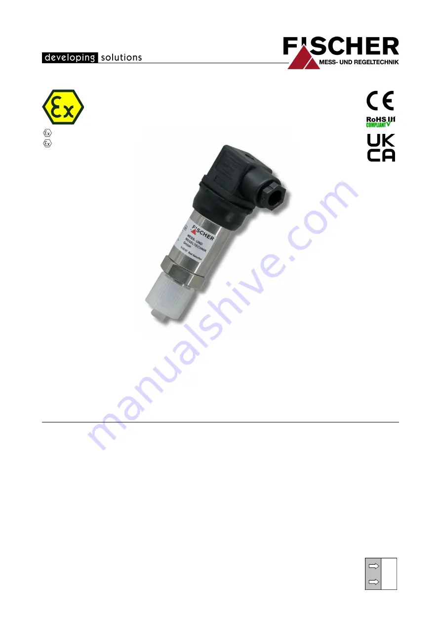
ME12 ... R/S

Remotely configurable digital pressure transducer

for use in explosive areas

Gas explosion protection Zone 2

Dust explosion zone 22

09005483 • BA_EN_ME12_ATEX • Rev. ST4-D • 04/22

*09005483*

Summary of Contents for ME12 R Series

Page 1: ...Ex tc IIIB T125 C Dc Operating manual ME12 R S Remotely configurable digital pressure transducer for use in explosive areas Gas explosion protection Zone 2 Dust explosion zone 22 09005483 BA_EN_ME12_A...

Page 2: ...s without the written consent of the company FISCHER Mess und Regeltechnik GmbH Bad Salzuflen Reproduction for internal use is expressly allowed Brand names and procedures are used for information pur...

Page 3: ...installation work 5 1 8 Pictogram explanation 5 2 Product and functional description 6 2 1 Product overview 6 2 2 Use as intended 7 2 3 Function diagram 8 2 4 Design and mode of operation 8 3 Installa...

Page 4: ...or explosion proof models the specialized personnel must have received spe cial training or instruction or be authorized to work with explosion proof instru ments in explosion hazard areas 1 3 Risks d...

Page 5: ...nance and installation work The safety instructions given in this operating manual any nationally applicable regulations on accident prevention and any of the operating company s internal work operati...

Page 6: ...ectors and process con nections The code stated corresponds to the respective code in the order code Electrical plug Standard casing Line socket DIN EN 175 301 803 A Circular plug connector M12 DIN EN...

Page 7: ...edia Please see the technical data for the re spective measuring ranges NOTICE Soiled or aggressive media Please contact the manufacturer before using this unit with dirty or aggressive media because...

Page 8: ...DMS principle The measured pressure acts directly onto a ceramic membrane that deforms when under pressure This changes the resistance of the attached DMS bridge Elec tronics integrated into the devi...

Page 9: ...lation however any installation posi tion is possible To guarantee safe working conditions during installation and maintenance suit able stop valves must be fitted in the system see accessories By mea...

Page 10: ...shape U shape G ca 180 20 56 155 ca 200 G G ca 275 ca 130 20 56 G AF27 Manometer connection Connection spigot according to DIN EN 837 1 Fig 6 Siphon MZ1 The transmitter must be positioned below the m...

Page 11: ...When connecting the unit the national and international electro technical regulations must be observed Disconnect the system from the mains before electrically connecting the device Install the consu...

Page 12: ...ocket Fig 11 M12 plug DIN EN 61076 2 101 Pin Signal name DC Cable colour 1 Supply Output Ub Sig brown 2 n c 3 Supply Output Ub Sig blue 4 n c Table 2 2 wire connection 4 20 mA 3 4 Commissioning All el...

Page 13: ...ve or faulty devices should be sent directly to our repair department Please coordinate all shipments with our sales department WARNING Process media residues Process media residues in and on dismantl...

Page 14: ...pressure Option 0 0 6 0 60 4 bar 7 bar 0 1 0 100 4 bar 7 bar 0 5 FS 0 1 6 0 160 4 bar 7 bar 0 5 FS 0 2 5 0 250 10 bar 15 bar 0 5 FS 0 4 0 400 10 bar 15 bar 0 5 FS 0 6 0 600 20 bar 35 bar 0 5 FS 0 10...

Page 15: ...40 bar 70 bar 1 24 100 2400 100 bar 150 bar 4 3 Output parameters 2 Conductor Output range 4 20 mA Limits ca 26 mA Apparent ohmic resist ance Ub 6V 0 02A 4 4 Measurement accuracy Non linearity Maximu...

Page 16: ...connection CrNi Steel 1 4404 Sensor membrane Ceramic Al2O3 Seal 1 FKM Fluorinated rubber Viton CR Chloroprene rubber Neopren EPDM Ethylene propylene diene rubber H NBR Hydrogenated acrylonitrile buta...

Page 17: ...sign 4 8 1 Dimensional picture M12x1 72 38 5 28 SK hex SW27 91 20 3 G 6 17 5 13 2 5 G 9 5 Fig 12 Standard casing dimensional drawing near flush mounted front sensor 18 NPT EXT Schrader G B G1 B 18 NPT...

Page 18: ...404 G B Connection shanks with external thread near flush mounted front sensor 1 4404 G1 B Connection shanks with external thread near flush mounted front sensor 1 4404 4 8 3 Electrical connection Fig...

Page 19: ...F4 0 250 kPa 05 0 4 bar F5 0 400 kPa 06 0 6 bar F6 0 600 kPa 07 0 10 bar F7 0 1000 kPa 08 0 16 bar F8 0 1600 kPa 09 0 25 bar G1 0 2500 kPa 10 0 40 bar G2 0 4000 kPa 11 0 60 bar G3 0 6000 kPa 31 1 0 b...

Page 20: ...ection H Cable socket DIN EN 175 301 803 M M12 coupling device DIN EN 61076 2 101 8 Operating voltage 9 24 V DC 2 wire version 9 Casing Protection class DIN EN 60 529 0 Standard casing IP65 V Standard...

Page 21: ...able with M12 coupling 4 pin 7m 06401572 PUR cable with M12 coupling 4 pin 10m MZ1 Siphons MZ400 Capillary throttle coil MZ410 Settable damping reactor MZ5 Manometer shutoff valve acc to DIN 16270 162...

Page 22: ...6 Attachments FISCHER Mess und Regeltechnik GmbH 22 24 BA_EN_ME12_ATEX 6 Attachments Fig 16 CE_EN_ME12_ATEX...

Page 23: ...FISCHER Mess und Regeltechnik GmbH Attachments 6 BA_EN_ME12_ATEX 23 24 Fig 17 UKCA_EN_ME12_ATEX...

Page 24: ...lefelder Str 37a D 32107 Bad Salzuflen Tel 49 5222 974 0 Fax 49 5222 7170 www fischermesstechnik de info fischermesstechnik de Technische nderungen vorbehalten Subject to technical changes Sous r serv...

Reviews: