3 | Assembly
FISCHER Mess- und Regeltechnik GmbH
22/108
BA_EN_FT90
3.4.4 Device with Modbus
DANGER
Auxiliary energy for ATEX devices
When selecting the power supply, bear in mind that it may be a potential ignition
source.
Take suitable safety precautions to prevent this risk.
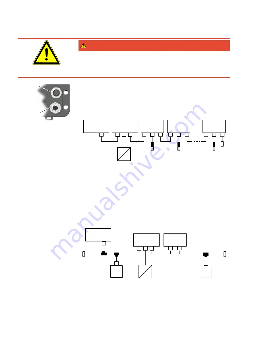
Modbus IN
Modbus OUT
1
2
Fig. 22:
Modbus replacement
plate
The devices with a Modbus interface do not have analog and switch outputs.
The replacement plate is equipped with a 5-pin M12 flange connector for the
Modbus input and a 5-pin M12 flange socket for the Modbus output.
The FT90 can be connected to the Modbus RTU network as a slave. Up to 247
devices can be addressed in one line network.
NOTICE! Star-shaped networks are not allowed.
MASTER
FT90
1
2
FT90
1
2
FT90
1
2
Address 1
Address 2
Address 247
Bus termination
AC/DC
AC
M
Supply
1
2
E
Modbus
5
3
T/RH
3
T/RH
3
T/RH
Fig. 23:
Modbus RTU network
Communication is effected solely with the Modbus master. The connected
slaves only react to direct commands from the master, so communication
between the slaves is not possible.
To guarantee fault-free data transmission, we recommend terminating the end
point of the Modbus RTU network with a 120 Ω resistor. This bus termination
resistor is available as an accessory.
3.4.4.1 Connection to an existing Modbus RTU network
It can be connected to an existing Modbus network via a conventional T-piece
(passive TAP).
MASTER
M
TAP
M
Slave
TAP
LT
LT
M
Slave
TAP
DE90
1
2
Supply
1
2
E
AC/DC
AC
Fig. 24:
Modbus connection


