fisair HEF7 Series Installation And Maintenance Manual Download Page 30


 HEF7 series manual  30 


16.  Maintenance and cleaning 


IMPORTANT 

Request maintenance of your units by contacting: 

[email protected]


[email protected]


https://

fisair.com/es/servicio/mantenimientos/ (application in Spanish) 

https://

fisair.com/service/maintenance/ (application in English) 
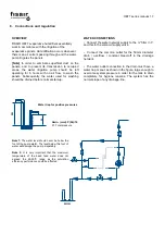


16.1. 

Evaporative humidification: a natural method that does not carry bacteria. 

The operational features of evaporative humidifiers are based on the natural effect of the water evaporation when an 

air flow goes through/by a wet surface (is the same natural principle that occurs when water evaporates from waterfalls, 

rivers, lakes, seas...). 


Evaporation means that the water leaves the humidifier as pure vapour (gas). Minerals and eventual pollutants stay in 

the water and can  be  eventually drained / eli

minated. With no droplets or aerosols carry over, the bacteria can’t be 

transferred to the humidified air. It is important to use a droplet separator when it’s needed. 


The evaporative humidifiers work with water temperatures below 24°C, very far from the optimal growth temperatures 

of the bacteria present in the water, essentially Legionella pneumophila, with an optimum growth temperature of 37-

41ºC. 


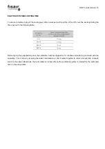
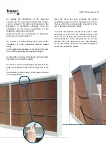
The water basin, manifold, irrigation system and the other components of the HEF2 series are specially designed for 

there to be complete emptying by gravity, without the aid of mechanical elements. Based on the quality of treated air 

and water supply, a cleaning and emptying inspection plan should be established. 

16.2. 

Cleaning 


16.2.1. 

General 

An inspection, emptying and cleaning plan must be established for the HEF2 Series depending on the treated air and 

feed water quality. 


Evaporation humidifiers should be cleaned regularly to prevent contamination. All the component surfaces (panel, pipes 

and especially the water deposit) must be disinfected with an appropriate solution.  


A cleaning process must be carried out once a year to maximize the useful life of the Cassettes. 


Special attention must be  paid to the cleanliness of the  piping system, especially where it diverts; and  the  cleaning 

process must reach all parts of the system. 


Summary of Contents for HEF7 Series

Page 1: ...6 info fisair com fisair com HEF7 SERIES INSTALATION AND MAINTENANCE MANUAL Adiabatic cooling system for Air condensed Water Chillers MHEF7 EN 21 0 In compliance with European Union standards for mach...

Page 2: ...HEF7 series manual 2...

Page 3: ...ion 19 10 Level detector connection 20 11 Solenoid valve electricity connection 22 12 Connection of the motor zone valve N C for automatic emptying draining 23 13 Setting the valve regulating irrigati...

Page 4: ...are laid out in criss crossing channels to provide a large surface area for air water contact which maximizes water evaporation and at the same time minimizes resistance to the air flow passing throu...

Page 5: ...amiliar with it before installing commissioning or servicing The following symbols or messages may appear in this document or on the equipment They warn of potential hazards or provide information tha...

Page 6: ...not be removed or disabled Installing Disassembling Maintaining and Repairing the unit The machine must not be manipulated when it is operating Switch off the unit s power supply when conducting maint...

Page 7: ...manual 7 2 HEF7 nomenclature HEF7 MODEL HEF7 VCS906 E6 Factory chiller model PUMPING GROUP FOR HEF7 Pumping group 230V IN 50 60Hz Line voltage Basic control panel CONTROL PANEL CCB2 0 230V IN 50 60Hz...

Page 8: ...ed into or assembled with other machinery or other partly completed machinery or equipment thereby forming machinery to which this Directive applies Therefore the HEF7 device is classified according t...

Page 9: ...HEF7 series manual 9 Machine type rating plate Partly completed machinery quasi machine type rating plate...

Page 10: ...m the evaporation Maximum freshness it works as a natural filter purifying the entry air Carefully designed channelling eliminates dust particles and mineral deposits from the air which are trapped on...

Page 11: ...ation and cooling even at high air speeds They are made of fireproof inorganic material They are ideal for humidifiers placed after air treatment and heater units and for the pre cooling of gas turbin...

Page 12: ...HEF7 series manual 12 5 Unit components 1 2 4 3 7 5 6...

Page 13: ...Cassette length H Cassette height E Cassette thickness For further information on parts of systems please contact the manufacturer Brand Code Descriptions Units 1 REGULATION VALVE 1 2 62000075 REGULAT...

Page 14: ...Supply B Constant bleed off C Overflow D Drainage 1 Regulation valves with Flow meter Irrigation 2 Regulation valves with Flow meter Bleed off 3 Filling Solenoid Valves 4 Max Min level detector 5 Valv...

Page 15: ...VICING SPACE Humidifiers are normally placed just before the coil and before the sensible exchange in the air cooling system A 1m space should be left in front of the unit section for inspection and s...

Page 16: ...ollowing table Before drying the evaporation panel the ventilation must be stopped for 10 minutes and watering continued with the cassettes This is done by keeping the water recirculation or direct wa...

Page 17: ...etwork supply to the filter in Y and this to the solenoid supply valve Connect the common outlet for the 50mm diameter drain overflow constant bleed off to the drainage network The water outlet connec...

Page 18: ...he main water supply line with continuous water flow 2m Install a 3 way valve before the cut off valve with a return line to the main water supply line to avoid water retention o If the distance from...

Page 19: ...ricity supply cable to the terminal box of the water irrigation pump using an appropriate connection IP 55 or higher La protecci n y operativa de alimentaci n el ctrica a la bomba debe ser determinada...

Page 20: ...it to this level so that it is cut for safety J16 sensor indicates maximum water level NC take a look on CCB2 0 manual Remark Max Voltage 175 Vcc 110 Vca Max Current 1 Acc Temperature 20 120 C Min De...

Page 21: ...be left without connection Mesh to fix the float Remark Remove the fixing mesh when the equipment is placed on its final location just before commissioning N C normally closed ALTO High level S2 N A n...

Page 22: ...NC solenoid valve of the tank is composed of the body of the valve the coil and the connector The coil and the connector are supplied for a 24Vac or 230Vac connection G brass water supply N C solenoid...

Page 23: ...C for automatic emptying draining Remark When this motor zone valve is connected to the CCB2 0 Basic Control Panel it will be necessary to connect the S4 cables Black Red and S6 ones Black Pink to the...

Page 24: ...HEF7 series manual 24 GMA12 1 GMA32 1 2 points control AC 24 V 2 points control AC 230 V Dimensions Electric Diagram connections...

Page 25: ...24 V DC 24 48 V G0 2 black BK System neutral Actuators AC 230 V L 3 brown BN Phase AC 230 V N 4 blue BU Neutral conductor Auxiliary switch Q11 S1 grey red GY RD Switch A input Q12 S2 grey blue GY BU S...

Page 26: ...lowing equation for calculating the total irrigation flow of each HEF 7 can be employed to set the regulation valve precisely n I e 60 ai i 0 I total unit irrigation e thickness of the evaporative cas...

Page 27: ...ppm pH 6 8 Silica SiO 30 ppm Iron Fe 0 2 ppm Oils and grease 2 ppm Total dissolved solids 550ppm Total alkalinity CaCo3 50 170 ppm Suspended solids 5 ppm Bleed off based on the cycle of concentration...

Page 28: ...by removing the handwheel from its parked position and placing it on the flow meter It can then be swivelled to set the required flow Once the flow has been set place the handwheel in its parked posit...

Page 29: ...ng air flow contamination and avoid extra foam formation it is recommended to repeat the following cycle for 6 periods 10 min of pump operation recirculating the water and then 10 min of emptying Rema...

Page 30: ...umidifiers work with water temperatures below 24 C very far from the optimal growth temperatures of the bacteria present in the water essentially Legionella pneumophila with an optimum growth temperat...

Page 31: ...tants are used they should not be mixed with an acid solution due to the potential formation of toxic chlorine gas Remark The manufacturer s safety steps for the disinfectant solution should be follow...

Page 32: ...days following start up to find out how the specific installation is behaving and to establish the emptying and cleaning programme Similarly during long periods of inactivity summer in the case of hu...

Page 33: ...hly recommended practice is to add water treatment to the humidifier supply In order to remove the evaporative cassettes from the units it is necessary to take off the upper front cover of the structu...

Page 34: ...17 Machine conformity declaration...

Page 35: ...18 Cuasi machine conformity declaration...

Page 36: ...19 WARRANTY...

Page 37: ......

Reviews: