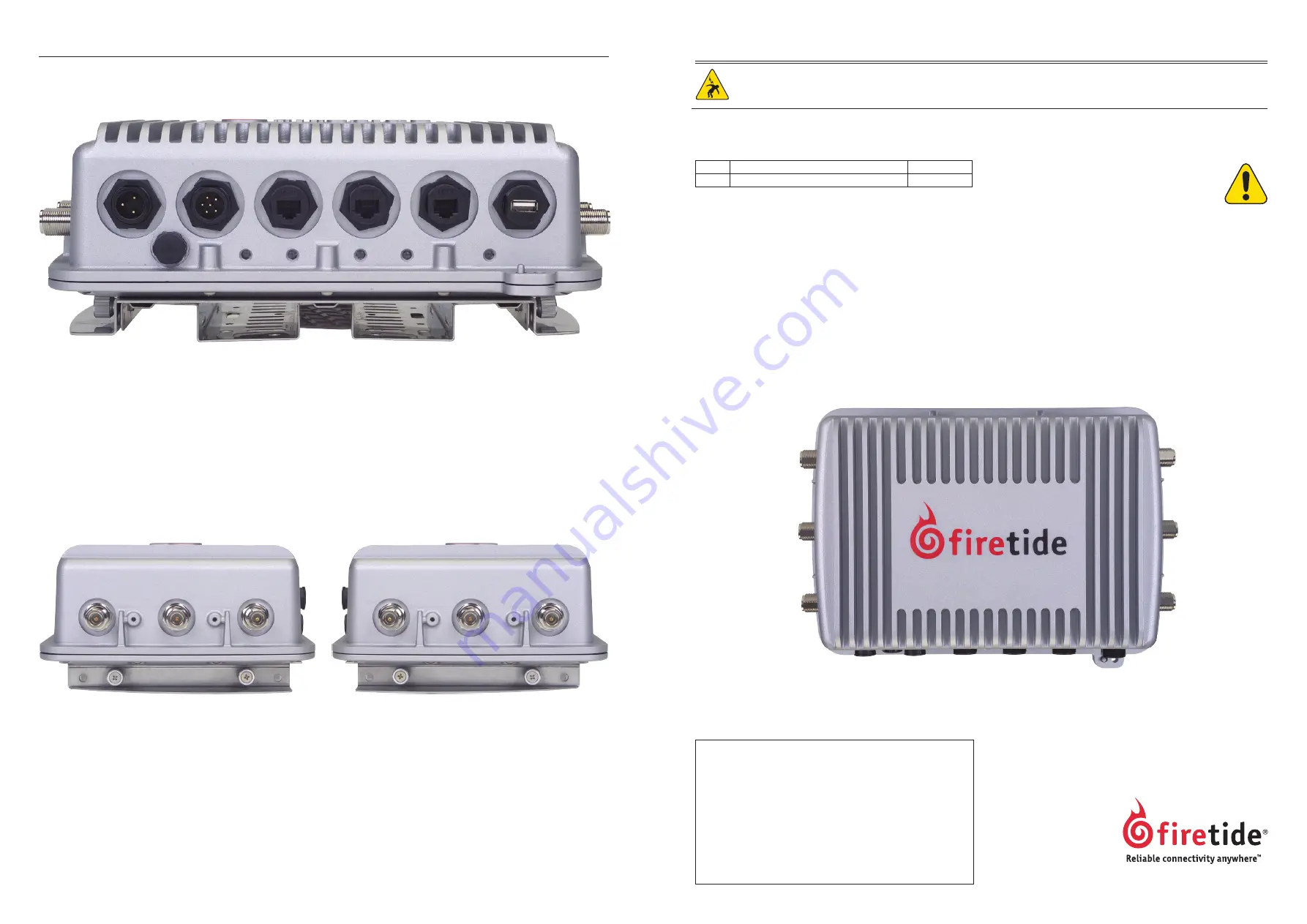
Connecting Cables
After your node is mounted, attach the antennas, the power cable, and any Ethernet cables you need. Note that all of the weath-
erproof caps have been removed from the node for illustrative purposes. You should not leave any unused connector uncovered.
HotPort 7200 Quick Install Guide
The HotPort is intended to be installed by trained profession-
als. Be sure to read and understand all installation and safety
instructions before proceeding with the installation.
Model Use
No. of Radios
7200 Outdoor, Worldwide, 2.4, 4.9, 5 GHz
1 or 2
The HotPort 7200 contains two radios. The number of radios
that will be active is determined by the license.
Package Contents
If you are missing any items, contact your Firetide reseller.
• HotPort in NEMA-4X enclosure with weatherproof caps.
• Six N to reverse-polarity SMA adapters.
• Mounting bracket for pole and wall mounting. Designed
to fit 37 mm to 50 mm (1.5 in to 2.0 in) poles.
• Mounting Kit
• U-Bolts, M6x1.0-80, w/flat and split washers, nuts.
• Claw-tooth pole grippers.
• M6x1.0-40mm hex bolt.
• M6x1.0-20mm hex bolt.
• Hex-head socket wrench.
• Temporary Staging Antennas
• Six 2.4 GHz omni-directional INDOOR antennas.
• Six 5 GHz omni-directional INDOOR antennas.
(Notes: Do not use antennas outdoors.)
• AC power cord.
• Documentation
• HotPort 7200 Quick Install Guide.
• Warranty and registration card.
• Compact Disk (CD)
• HotView software.
• HotView Pro User Guide.
• HotPort Series 7000 Hardware Installation Guide.
• Warranty/Registration Card.
• EULA.
Required Tools and Supplies
• #2 Phillips screwdriver.
• Small adjustable wrench.
• 10 AWG grounding cable, connectors and rod.
• Weatherproofing kit – this kit provides electrical tape and butyl
mastic.
• Hose clamps, band clamps, U-bolts, or similar brackets, suitable
for mounting your antennas to your chosen antenna mast.
Depending on the installation location, you may need ladders, a lift
truck, or other means to access the actual installation locations.
Caution! Risk of electric shock!
POWER LINES CAN BE LETHAL: Every year, people are killed by
touching overhead power lines. Don’t be one of them.
Document Revision 1.00 2009-08-01
Subject to change without notice.
port 1
port 2
port 3
dc power
usb
ac power
power
status
radio 1
radio 2
ethernet
–mesh–
Note the location of the reset button under the weatherproof cap. To perform a factory reset on the unit, power it on and wait
for the status light to come on. Then press and hold the reset button until the status light blinks.
Connect the supplied AC power cable to AC power and to the HotPort node. Information on building custom power cables is shown
in the Installation Guide on your CD. Do not connect both AC and DC supplies simultaneously.
Ports 2 and 3 on a Series 7200 node can provide Power over Ethernet (PoE) functionality to Powered Devices (PD) connected to
these ports. (Port 1 cannot.) A Powered Device can receive data and the power to process the data from the HotPort node, which
functions as Power Sourcing Equipment (PSE) in this configuration. To receive power from a HotPort node, the device must sup-
port the IEEE 802.3af standard, which defines PoE functionality.
Don’t forget to order your permanent outdoor antennas! You can’t use the staging antennas outdoors, they might fail.
When connecting antennas, connect them in numerical order 1-2-3. If you are not using three antennas per radio, do not ‘skip’
antenna connectors. The antenna 1 connector is at the top of the unit (farthest from the power and Ethernet connections) on
both the left and right side.
antenna 2
antenna 1
antenna 3
radio 1
antenna 2
antenna 3
antenna 1
radio 2


