background image


Local Application Fire System 

FP-08917 

Rev 3.1


Page  |  4 

4


Installation 

4.1


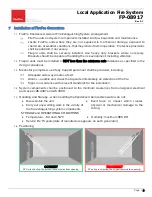
FirePro  Aerosol  Genrators  must  be  selected  in  accordance  with  approved  FirePro  design 
calculations and guidelines.   FirePro Brackets must be  installed using  Bolts 

  Tec Screws  will 

vibrate loose in vehicle/marine installations.  

4.2


FirePro units have a self-activation temperature of 300

C.  Placement of units should be carefully 

selected. 

4.3


All cabling in the FirePro Installation MUST be Installed using min 0.75mm shielded Fire Rated 
Cable  

4.4


Power MUST be connected directly power supply OR Battery to ensure operation of the system.  

 30v DC.  5A fuse or circuit breaker to be installed on power supply. 

4.5


Manual Actuator(s) where installed, placement is to be carefully considered 

 ensure that it is 

easily accessible in case of emergency.   Follow instructios for the installation of the FP-14053 
switch. 

4.6


Linear Heat Detection where installed, the system will activate automatically.  Follow instructions 
as per FP-09510 product manual. 


Incorrect installation may cause activation. 

4.7


Cable  Requirements  -  All  cabling  in  the  FirePro 
Installation  MUST  be  done  using  0.75mm  shielded 
Fire  Rated  Cable.    Care  taken  to  ensure  that  all 
cables are isolated, and that RF shielding on cable is 
stripped back to ensure that there is not accidental grounding.  Cables are colour coded for easy 
identification. 

4.8


Extension  Leads  -  Deutsch  Plugs  must  be  used  to 
ensure 

water-proof 

connections 

are 

made 

throughout the installation.   


Colour 

Circuit 


Red 

Power 


Yellow 

Activation 


Green 

Detection / Manual Switch 

Summary of Contents for FP-08917

Page 1: ...ge 1 CONTENTS 1 General Operations 2 2 Components 3 3 Specifications 3 4 Installation 4 5 Servicing Maintenance 5 6 Operation Activation 5 7 Installation of FirePro Generators 6 8 Connection of Multip...

Page 2: ...he switch 1 3 Power Supply designed to operate on 6 to 30vDC supply Number of FirePro units will depend on incoming power supply 1 4 A thermal Fuse FP 08825 may be connected to give a signal that syst...

Page 3: ...ch Plug for easy install FP 6100 Heavy Duty Bracket 316 SS Suits FP 1200 2000 3000 5700 FirePro Aerosol Generators Detection Circuit FP 9510 Linear Heat Detection Cable 182 C Supplied in Cut Lengths w...

Page 4: ...4 5 Manual Actuator s where installed placement is to be carefully considered ensure that it is easily accessible in case of emergency Follow instructios for the installation of the FP 14053 switch 4...

Page 5: ...connected Note the FirePro Simulator stay illuminated until the reset button on the simulator is pressed 5 4 Reconnect the FirePro activation circuit System Logbook A logbook must be kept recording a...

Page 6: ...prompt rescue of any trapped personnel shall be provided including Adequate aisle ways routes of exit Alarms audible and visual that operate immediately on detection of the fire Signs in accordance w...

Page 7: ...e control panel For ease of install servicing and more efficient field wiring Splitter Leads should be installed in areas easy to access and minimise extension leads Installation 8 1 FirePro generator...

Page 8: ...ntre If swallowed IMMEDIATELY contact Doctor or Poisons Information Centre show this container or label This material and its container must be disposed of as hazardous waste FIRST AID MEASURES SWALLO...

Reviews: