EQUIPMENT:
FIRE
CLASS
PRECEPT EN
WRITTEN BY: RKP
PUBLICATION:
FIRECLASS PREC EN OUTPUT EXP MOD INST
CHECKED BY: AP
ISSUE No. & DATE:
0 02/03/12
PAGE 14 of 21
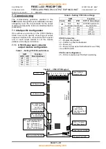
7.1.3 C1630 Output Interface
Configuration
Table 10
– Setting Quantity and Type of O/P
Modules on the C1630
DIL Switch
setting
Number
of boards
Type of board
F/P0
F/P1
C1634 or C1635
configured to FP [Fire
protection Output]. See
C1635 configuration
details.
Off
Off
0
On
Off
1
Off
On
2
On
On
4
S/C0
S/C1
C1635 configured as
sounder module. See
C1635 configuration
details.
Off
Off
0
On
Off
1
Off
On
2
On
On
4
LED0 LED1
C1633 open collector
output module
Off
Off
0
On
Off
1
Off
On
2
On
On
4
VDR
Not used on Precept
EN
Off
-
-
On
-
-
[Note: Select switch to left hand side for OFF and
right-hand side for ON]
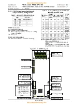
Figure 11
– C1630 output expansion interface
board
LED 0
S/C 1
S/C 0
F/P 1
F/P 0
1
2
3
4
5
6
LED 1
7
VDR
Configuration Switch
to set quantity & type
of modules connected.
7.2 Commissioning Procedure
After completion of the pre-commissioning wiring
check, power-up and configuration, commission the
circuits in line with the following guide.
7.2.1 Sounder Circuits
1. Remove the resistor from the first alarm circuit
terminal and connect the first alarm circuit wiring
to the terminals, observing correct polarity.
Check that any alarm fault indications clear after
a few seconds.
2. Use the Alarm Test facility [see
FIRE
CLASS
Precept EN User Manual] or press Evacuate to
operate the sounders. Check that all sounders
connected to the alarm circuit operate.
3. Deselect the Alarms Test condition or if
“Evacuate” was used, press silence alarms to
stop the sounders operating.
4. Repeat steps 1 to 3 for the second and any
subsequent sounder circuits.
7.2.2 Powered/fault monitored Fire
Protection outputs
[C1635 modules configured as Fire Protection
O/Ps]
1. Ensure any fire protection equipment to be
controlled via the Fire Protection output is locked
off/safe before attempting any connection,
testing or commissioning.
2. Remove the resistor from the C1635 output
circuit terminal and connect the field wiring to
the terminals, observing correct polarity. Check
that any fault indications clear after a few
seconds.
3. Initiate a fire condition on a zone to operate the
output. Check that the fire signal operates the
remote interface relay adjacent the fire
protection equipment.
4. Reset the panel and confirm that the remote
interface relay deactivates.
5. Open-circuit the field wiring and confirm that the
fire alarm panel indicates Fire Protection output
fault.
6. Reconnect the cabling and confirm the faults
clear.
7. Disable the Fire Protection Outputs via the
Precept EN panel [see Precept EN Operating
Instructions]. Initiate a fire condition on a zone to
operate the output and check that the output
does not operate. Reset the panel and re
–
enable the Fire Protection O/Ps after the test.
8. Final testing and commissioning of the loop
through to the fire protection equipment,
including test [simulated] activation of the
equipment, should be carried out at the
appropriate time in conjunction with the engineer
responsible for the fire protection system.
9. Repeat steps 1 to 7 for the second and any
subsequent fire protection signal outputs.
7.2.3 Volt-free relay Fire Protection
outputs
[C1634 modules configured as Fire Protection
O/Ps]
1. Ensure any fire protection equipment to be
controlled via the Fire Protection output is locked
off/safe before attempting any connection,
testing or commissioning.


