background image

EQUIPMENT:


FIRE

CLASS 

PRECEPT EN 


WRITTEN BY: RKP 

PUBLICATION:


FIRECLASS PREC EN OUTPUT EXP MOD INST 

CHECKED BY: AP 

ISSUE No. & DATE:


0      02/03/12


PAGE 12 of 21 

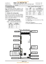
Table 5 

– Setting C1634 Board Address 

SW1 

Function 

AD0 

AD1 

Board Address 

Off 

Off 

On 

Off 

Off 

On 

On 

On 


Table 6 

– Setting C1634 Zone Range 

SW1 

Function 

Zonal 

ZN0 

ZN1 

O/P 1-8 zone 

range 

Off 

Not 

functional 

Not 

functional 

All O/Ps 

operate on 

any zonal fire 

On 

Off 

Off 

Z 1-8 

On 

On 

Off 

Z9-16 

On 

Off 

On 

Z17- 24 

On 

On 

On 

Z25 -32 

Table 7 

– Setting C1634 Function 

SW1 

Function 

Off 

Fire Protection module 

On 

Voyage Data Recorder [Marine 
Panels only] 


C1634 Connectors:


J1 

– Programming header. 

J2 

– Comms and power from panel motherboard. 


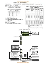
Figure 9 

– C1634 PCB Layout 

ZONAL

ZN1

ZN0

AD1

AD0

1

2

3

4

5

SW1

J3

J2

S

W

2

PROC FAULT

RESET

C

O

M

S

F

L

T

P

R

O

C

F

L

T

P

S

O

N

C

E

L

 C

1

6

3

4

IS

S

U

E

 2

0

5

-0

5

-2

0

0

5

8 WAY RELAY BOARD

1

OP1

J2 Comms In/Out

J3 Comms In/Out

Relay Outputs:
N/O 

– normally open

POLE 

– common

N/C 

– normally closed

SW2 

– Processor 

Fault Reset Button

Power Supply ON LED

Processor Fault LED

Communication Fault LED

SW1 

– Configuration Switch.

AD0 

– Address bit 0

AD1 

– Address bit 1

ZN0 

– Zone range bit 0

ZN1 

– Zone range bit 1

ZONAL 

– Zonal response

VDR 

– Voyage Data 

Recorder output mode 
(for Marine Panel Use 
only)

OP2 OP3 OP4 OP5 OP6 OP7 OP8

2 3 4 5 6 7 8

N

/C

N

/O

P

O

L

E

6

VDR


www.acornfiresecurity.com

www.acornfiresecurity.com

Summary of Contents for Precept EN Panel

Page 1: ...PAGE 1 of 21 Precept EN Output Expansion Module Installation Commissioning Manual www acornfiresecurity com www acornfiresecurity com...

Page 2: ...1634 FIELD WIRING CONNECTIONS 3 FIGURE 3 C1635 FIELD WIRING CONNECTIONS 3 FIGURE 4 PRECEPT EN 16 INTERNAL VIEW SHOWING OPTIONAL SINGLE O P BOARD 4 FIGURE 5 PRECEPT EN 16L INTERNAL VIEW 32 ZONE ENCLOSU...

Page 3: ...The FIRECLASS Precept EN 16L fire alarm panel uses the C1652 230Vac 5A PSU mounted on the internal chassis beneath the motherboard output modules FIRECLASS Precept EN Exp 4 and 5 output expansion pane...

Page 4: ...mary Earth Connection Removable Chassis Relay output Module Batteries Motherboard C1630 Output Expansion Interface Board Removable Chassis Figure 5 Precept EN 16L internal view 32 zone enclosure with...

Page 5: ...Exp 5 internal view Mains Warning Primary Earth Label Cable Clip for incoming mains cable 3 x Enclosure fixing holes Secondary Earth bars for cable screens Mains Terminal Block and primary Earth Conn...

Page 6: ...ake great care when lifting and transporting batteries For weights above 24 kilos lifting aids should be used DANGER Do NOT attempt to remove the battery lid or tamper with the internal workings of th...

Page 7: ...rol panel remove the chassis from the output expansion panel generally as described in the FIRECLASS Precept EN panel installation manual carefully remove the 25mm knock outs in the adjoining faces of...

Page 8: ...bbon Motherboard C1627 connector J17 Connector J2 on O P module 1 left hand most module Figure 15 Aux DC power cable Motherboard C1627 power out connector J24 Power in connector on the first C1633 C16...

Page 9: ...1635 8 zone with 1 O P module Exp 4 or Exp5 with power supply Data Ribbon Data out connector on the O P module J6 on C1633 and C1635 Connector J2 on O P module 1 left hand most module Figure 16 Aux DC...

Page 10: ...fit a C1630 output expansion interface to connectors J4 and J5 see Figure 7 J21 must be removed before the interface board can be fitted The board should be held in place by the 12mm high plastic spac...

Page 11: ...ctional All O Ps operate on any zonal fire On Off Off Z 1 8 On On Off Z9 16 On Off On Z17 24 On On On Z25 32 C1633 Connectors J1 Programming header J2 Comms to panel motherboard J3 Power out J4 Power...

Page 12: ...er Marine Panels only C1634 Connectors J1 Programming header J2 Comms and power from panel motherboard Figure 9 C1634 PCB Layout ZONAL ZN1 ZN0 AD1 AD0 1 2 3 4 5 SW1 J3 J2 SW2 PROC FAULT RESET COMS FLT...

Page 13: ...n FP N A On On Off Z9 16 On FP N A On Off On Z17 24 On FP N A On On On Z25 32 Notes SNDR Sounders FP Fire Protection When panel SW 2 6 is on If panel SW2 7 is off non alarm zones are silent If panel S...

Page 14: ...and any subsequent sounder circuits 7 2 2 Powered fault monitored Fire Protection outputs C1635 modules configured as Fire Protection O Ps 1 Ensure any fire protection equipment to be controlled via...

Page 15: ...one to operate the output and check that the output does not operate Reset the panel and re enable the Fire Protection O Ps after the test 6 Final testing and commissioning of the loop through to the...

Page 16: ...4 way O P enclosure with max 4 O P modules with or without optional 5 Amp PSU and batteries 5 Precept EN 32 with Exp 5 5 way O P enclosure with max 5 O P modules with or without optional 5 Amp PSU an...

Page 17: ...ith max 5 O P modules with or without optional 5 Amp PSU and batteries C1634 J2 Data ribbon Aux DC J17 J24 C1627 Motherboard Precept EN Exp 4 4 way O P expansion enclosure with 4 modules powered from...

Page 18: ...ulation must be carried out for each application Aux DC TB1 28V 0V MFlt CFlt TB5 J1 PWR Flt O Ps C1652 5 Amp PSU Aux DC Mains Flt Comm PSU Flt Aux DC or use additional PSU J2 C1635 J6 J2 C1635 J6 Note...

Page 19: ...s Data ribbon Precept EN 32 with 5 Amp PSU Precept EN Exp 5 5 way O P expansion enclosure C1627 Precept EN Motherboard Aux DC Further expansion modules PSU load calculation must be carried out for eac...

Page 20: ...re with 4 modules powered from the Precept EN panel Aux DC Note All C1634 modules must be connected at the end of the sequence J2 C1633 J6 J4 J3 J2 C1633 J6 J4 J3 J2 C1635 J6 J3 J5 J3 C1634 J2 J3 Aux...

Reviews: