background image

20

TECHNICAL SPECIFICATIONS

IR lens
(Lens extension for 
high installations)

Button

Battery lid
(Battery 1 x CR2032)

Signal LED
should face towards use

•  Voltage  230–400 VAC

•  Extremely low energy  

use (approx. 1 W)

•  Automatic electrical  

switch

•  For safe connections 

up to 10 mm

2   

wires

•  Alarm signal 80 dB(A) @ 1 m  •  RF 433 MHz  •  Patented EP1861839,  EP2902710  
• 

Fulfils EN 50615:2015 Standard for stove guards (Eurofins Expert Services Oy)

THE HEAT SENSOR

THE CONTROL UNIT

THE JUNCTION BOX

3

Summary of Contents for Stove Guard FSG 1

Page 1: ...INSTALLATION OPERATING INSTRUCTIONS Kitchen STOVE GUARD FSG1...

Page 2: ...with local regulations For indoor use only Do not use in a professional kitchen Do not hold the Heat Sensor close to the ear It can cause hearing damage when in alarm or test mode Do not leave childre...

Page 3: ...se alarms 14 After alarm Cookers with mechanical controls 14 After alarm Cookers with touch controls 14 Dislocation alarm 14 Action in the event of an alarm 15 Other settings 16 17 Changing the sensit...

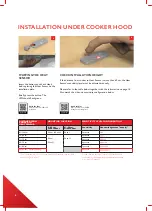
Page 4: ...irectly above the centre of the cooker under the cooker hood The Heat Sensor can also be mounted on a wall with a mounting bracket or on the ceiling Follow these instructions for correct installation...

Page 5: ...neath the hood is 10 cm 5 cm is enough for LED lamp Please note Zone 1 is recommended for best performance 1 Measure distance SELECTING THE MOUNTING LOCATION If there is a metal mesh grease filter on...

Page 6: ...The installation may not in all cases meet all EN standard requirements See FAQ page 18 point 4 Please note the sensitivity level of the Heat Sensor is confirmed by the appropriate sound pattern sequ...

Page 7: ...the installation plate Press for at least a minute while attaching installation plate to allow adhesive to work 1 Mounting height on the wall above the cooker Max 90 cm wide cooker Recommended 80 cm A...

Page 8: ...ble below together with the information on page 16 Also watch the video on sensitivity configuration below DISTANCE FROM COOKER TO HEAT SENSOR SENSITIVITY LEVEL CONFIGURATION Sensitivity Acknowledgeme...

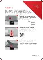
Page 9: ...cooker and ceiling Place the Heat Sensor directly above the center point of the cooker Make sure that the surface is clean and dry MOUNTING THE INSTALLATION PLATE Make sure that the ceiling is free of...

Page 10: ...CE FROM COOKER TO HEAT SENSOR SENSITIVITY LEVEL CONFIGURATION Mounting height above the cooker 0 90 cm wide cooker Sensitivity Number of beep s 160 200 cm Recommended Immediately above the middle of t...

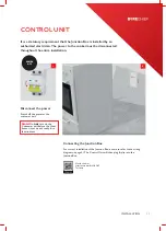
Page 11: ...onnect the power Switch off the power at the consumer unit Note Do not turn on the Consumer unit before the Heat Sensor is set up and ready for a function test Connecting the Junction Box For correct...

Page 12: ...he cooker and give an alarm signal every 5 seconds The Heat Sensor will also emit a test alarm after a few seconds Note Ensure that there is no power going to any of the cooking plates Reset the alarm...

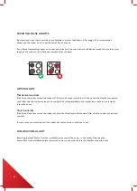
Page 13: ...s situation press the button to indicate that the situation is safe The Heat Sensor has then learned more about your cooking habits and you can continue cooking Please note When installing the Heat Se...

Page 14: ...off first turn all cooker controls to 0 then press the Heat Sensor button once After this the cooker can be used normally With ceiling installation the reset button needs to be pressed to return the...

Page 15: ...sure that the controls are set to 0 Wait until the cooker has cooled down after it has been disconnected then press the Heat Sen sor button once to return the power If the cooker cannot be switched b...

Page 16: ...be input Note When selecting the correct sensitivity level it is important the process is not rushed Ensure the sensor button is pressed down firmly each time holding for 1 second before releasing Be...

Page 17: ...hecking sensitivity level Watch the film https youtu be uJ4T_gMJApQ Reset to factory settings PAIRING DEVICES The units are already paired at the factory When replacing the Heat Sensor or the Control...

Page 18: ...en seconds may be triggered if the Heat Sensor is not on the installation plate if it is positioned incorrectly or if it is covered by dirt or grease It can also be triggered by a problem with the rad...

Page 19: ...ed an adapter plate that allows the use of all cookware on an induction cooker available from many retailers or an induction suitable cooking vessel Place the adapter plate on a cooker and perform a h...

Page 20: ...ace towards use Voltage 230 400VAC Extremely low energy use approx 1 W Automatic electrical switch For safe connections up to 10 mm2 wires Alarm signal 80 dB A 1 m RF 433 MHz Patented EP1861839 EP2902...

Page 21: ...stallations with parallel connected relays Type 1 or equivalent circuit breaker MCB shall be used for protecting the Stove Guard supply The circuit breaker shall have capability of interrupting the su...

Page 22: ...where it will be accepted free of charge The product can be returned to your local retailer when purchasing a corresponding new product Proper disposal of this product helps to save valuable resource...

Page 23: ...23 NOTES...

Page 24: ...T 0330 999 0019 E sales firechiefglobal com www firechiefglobal com...

Reviews:

Related manuals for Stove Guard FSG 1