Solar inverter
UNO-DM-COM KIT
UNO-DM-PLUS Ethernet COM KIT
Quick installation guide
Page 1: ...Solar inverter UNO DM COM KIT UNO DM PLUS Ethernet COM KIT Quick installation guide ...
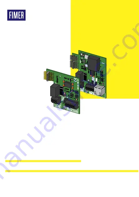
Page 2: ...g table Components supplied with the kit 01 Inverter connector 02 RS485 Line Termination Jumper 03 DRM0 Activation Jumper 04 Alarm Connector 05 Fixing hole 06 RS485 and REM connector 07 Ethernet communication port RJ45 08 EMI ferrite K1 J2 J3 1 J4 MP1 T R RTN RTN RS485 REM T R R 120 TERM ON OFF DRM0 N C N O ALARM C UNO DM COM KIT 01 05 04 06 03 02 05 04 06 07 03 02 01 08 ...
Page 3: ...talled inverter The installation must be performed by an installer or by a trained technician after reading the instructions given in this guide The board is directly powered by the inverter and provides the required safety isolation from the primary side of the inverter Only available on UNO DM PLUS Ethernet COM KIT board The Ethernet connectivity is based on Zero Conf IP protocol with DHCP clien...
Page 4: ...gland remove the M25 protection cap from the inverter and replace it with the cable gland fastening it with the same M25 lock nut and the same O ring of the protection cap ATTENTION A Caution To ensure the degree of environmental protection IP65 it is necessary to fix the cable gland to the inverter chassis with a minimum torque of 7 5 Nm When installing the cable gland M25 use the O ring removed ...
Page 5: ...he wiring box Run the cables inside the inverter through the hole and connect the cable to the accessory board 1 2 3 08 ATTENTION A The communication cable ethernet and or RS485 must be wrapped around the EMI ferrite 08 supplied in the package 1 winding such a EMI ferrite should be appropriately placed on the inside bottom side of the inverter compartment see side illustration and ethernet RS485 c...
Page 6: ...and D Firmly screw the thread lock sealing nut A B C D The characteristics required for the ethernet cable are listed in the table below Type Cable diameter CAT 5E or greather 6 mm max The ethernet cable must also be wrapped around the EMI ferrite supplied in the package 1 winding such a EMI ferrite should be appropriately placed on the inside bottom side of the inverter compartment 1 2 3 7 RS485 ...
Page 7: ...rther details on the operation modes of the Alarm terminal ATTENTION A The ALARM contact can only be used with systems that include additional safety insulation supplementary insulation in relation to the DC input voltage Using the REM terminal The REM terminal 06 when properly configured allows the use of the Remote ON OFF or the DRM0 functions The inverter can be disconnected from the grid remot...
Page 8: ... the contents partial or complete without the written consent of FIMER is prohibited Copyright 2021 FIMER All rights reserved 26 04 2021 9 Features and Technical Data Connections Type of connectors Connectors with spring Cables accepted 0 2 1 5 mm 24 16 AWG Ethernet 10 100Mbits base T only on UNO DM PLUS Ethernet COM KIT Alarm relay rating Floating contact 230V 1A max Remote On Off Digital input S...