


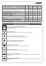


TECHNICAL DATA
U/M
SI
[KMS]
MMg
MMg
Cylindrical
MMg
Orbital
Battery compartment dimensions (length - width - height)
mm
525
385
300
525
385
300
525
385
300
Weight of batteries used for test [four 6V batteries, model 6TP210]
kg
129
129
129
Machine net weight [IEC 62885-9]
kg
267
265
253
Machine weight during transport [IEC 62885-9]
kg
396
394
382
GVW [IEC 60335-2-72; IEC 62885-9])
kg
609
601
585
Sound pressure on the operator's ears (Lp
A
) [ISO 11201, ISO 4871, EN 60335-2-
72]
dB (A)
63,3
63,3
63,3
Uncertainty Kp
A
dB (A)
1.5
1.5
1.5
Vibration level on the operator's arms [ISO 5349-1, EN 60335-2-72]
m/s
2
< 2.5
< 2.5
< 2.5
Vibration level on the operator's body [ISO 5349-1, EN 60335-2-72]
m/s
2
< 0.5
< 0.5
< 0.5
Vibration measurement uncertainty
1.5%
1.5%
1.5%
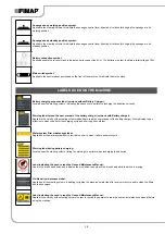
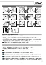
SYMBOLS USED ON THE MACHINE
Symbol of maximum temperature for filling the solution tank:
Applied to the left-hand side of the machine's solution tank to indicate the maximum temperature of the water that can be
used to safely fill the solution tank.
Filter body position symbol:
Applied to the left-hand side of the machine to indicate the position of the solution tank's filter.
P
Extra pressure activation/deactivation lever position symbol:
Applied to the central brush head's extra pressure activation/deactivation lever.
R
Reverse gear activation/deactivation lever position symbol:
Applied to the reverse gear activation/deactivation lever.
Recovery tank drainage hose symbol:
Applied to the back of the machine to identify the recovery tank's drainage hose.
Solution tank drainage cap symbol:
Applied to the back of the machine to identify the solution tank's drainage cap.
Brush head body working position symbol:
Applied to the steering column to indicate the brush head control lever direction of rotation for bringing the brushes to their
working position.
Brush head body standby position symbol:
Applied to the steering column to indicate the brush head control lever direction of rotation for bringing the brushes to their
standby position.
9