background image

10

LIGHTING

Prior to lighting your barbeque,visually check all hoses before each
use for nicks, cracking, abrasions or cuts. If the hose is found to be
damaged in any way, 

DO NOT USE YOUR BARBEQUE

. A

replacement hose and regulator is required (see ‘

PARTS LIST

’ in

Assembly Brochure).

IMPORTANT

•  Always raise the barbeque lid before lighting. 
•  Do not lean over the barbeque when lighting the burner.  
•  Visually check the flames every time you light your barbeque 

(Figure 10). If the flame is abnormally small or a smoky yellow -- 
shut off the barbeque and check the venturi tubes for blockage 
(see Figure 8) or refer to the Troubleshooting Guide.

MAIN BURNERS

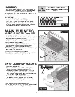
USING THE IGNITOR (Figure 11A)

1.Open the lid before lighting.
2.Turn off all of the burner control knobs and close the gas supply valve.
3.Open the gas supply valve and wait 5 seconds.
4.Push in and turn a single main burner control knob to ‘HIGH’. 

All other control knobs should be in the "OFF" position. 

5.Depress the ignitor, repeat if necessary.  
6.If the burner does not light immediately (within five  seconds), turn 

burner control knob off and wait 5 minutes to clear the gas.

7.Repeat steps 1 to 6. If burner still fails to light, refer to 

Troubleshooting Guide

to determine cause and solution, or try the 

Match Lighting procedure (Fig. 11B).

CAUTION

!

IF LIGHTING MAIN BURNERS ONLY, 

ENSURE SIDE BURNER KNOB IS IN THE OFF

POSITION.

MATCH LIGHTING PROCEDURE

1. Open the lid before lighting.
2.  Place an ignited lighter or lit match through the lighting hole, 

approx. 1.25 cm (1/2") from burner. (See Figure 11B)

3. Push in and turn the left burner control knob to ‘HIGH’. The 

burner should  light immediately (within five seconds). If it 
does not, extinguish the lighter or match, turn the control knob
to off, and wait 5 minutes to clear the gas. 

4.  Repeat steps 1 to 3. If burner fails to light, refer to the 

Troubleshooting Guide to determine cause and solution.

5.  Once left hand burner is lit, light remaining burners in this 

sequence: center burner, then right burner.

1.

Fig. 11A

Fig. 11B

HIGH

LOW

Fig. 10

LIGHTING THE OTHER MAIN BURNERS

Once one burner has been lit, push in and turn the adjacent control
knob to ‘HIGH’. The unlit burner will light automatically.

4.

5.

BURNER

MATCH

MATCH

LIGHTING

HOLE

LIGHTING THE OTHER MAIN BURNERS

Once one burner has been lit, push in and turn the adjacent control
knob to ‘HIGH’. The unlit burner will light automatically.

Summary of Contents for Blue Ember Grills FG50057

Page 1: ...e or use gasoline or other flammable liquids or vapors in the vicinity of this or any other appliance 2 An LP cylinder not connected for use shall not be stored in the vicinity of this or any other appliance DANGER Hazardous Fire or Explosion may result if these instructions are ignored It is your responsibility to see that your new barbeque is assembled installed maintained and cared for properly ...

Page 2: ...Y WARNING WARNING INDICATES AN POTENTIALLY HAZARDOUS SITUATION WHICH IF NOT AVOIDED COULD RESULT IN DEATH OR SERIOUS INJURY CAUTION CAUTION INDICATES AN POTENTIALLY HAZARDOUS SITUATION OR UNSAFE PRACTICE WHICH IF NOT AVOIDED COULD RESULT IN MINOR OR MODERATE INJURY WARNING Combustion by products produced when using this product contain chemicals known to the state of California to cause cancer bir...

Page 3: ...ND UNDERSTOOD ALL THE INFORMATION IN THIS MANUAL IT IS EXTREMELY IMPORTANT TO BE SURE THAT FAILURE TO ENSURE THE ABOVE MAY RESULT IN A HAZARDOUS FIRE OR EXPLOSION CAUSING SERIOUS BODILY INJURY AND OR PROPERTY DAMAGE 61cm 24 46cm 18 Fig 2 3 10mm MODEL MAY NOT BE EXACTLY AS SHOWN WARNING WARNING WARNING DO NOT USE THIS GAS OUTDOOR APPLIANCE UNDER ANY OVERHEAD COMBUSTIBLE CONSTRUCTION WHEN DECIDING W...

Page 4: ... valve outlet You may damage the back check A damaged back check can be the source of a leak Leaking propane may result in explosion fire severe personal injury or death Never fill the cylinder beyond 80 full Any attempt to connect a regulator with other than the i Mating Type 1 connector recognized by the large black coupling nut or ii Standard 510 P O L fitting by use of adapters or any other me...

Page 5: ...ll or repair your cylinder DO NOT allow the cylinder to be filled beyond 80 full Make sure the L P gas dealer checks the cylinder for leaks after filling LP CYLINDER EXCHANGE Many retailers that sell grills offer you the option of replacing your empty LP cylinder through an exchange service Use only those reputable exchange companies that inspect precision fill test and certify their cylinders Exc...

Page 6: ...gulator preset to this pressure is supplied with the barbeque and MUST be used This regulator is equipped with the Q C C Type 1 quick connect coupling system which incorporates the following safety features Figure 5 It will not allow gas to flow until a positive seal has been made Figure 6 It has a thermal element that will shut off the flow of gas between 115 and 150 C 240 and 300 F It also has a...

Page 7: ...y as well as contribute to the safe operation of this unit perform all of the operations below at least once a year preferably at the start of each cooking season PERFORM A LEAK TEST A leak test ensures that there are no gas leaks prior to lighting your barbeque WHEN A LEAK TEST MUST BE PERFORMED Before lighting your barbeque for the first time Every time the propane cylinder is refilled If any ga...

Page 8: ...RTS Wash with warm soapy water and wipe dry A Do not use citrisol abrasive cleaners degreasers or a concentrated grill cleaner on plastic parts Damage to and failure of parts can result 8 CASTING INTERIOR AND WARMING RACK At least once a year remove all components from inside your barbeque Loosen any cooking residue with a scraping tool for large particles and a brass barbeque brush for smaller pa...

Page 9: ...gure 9A If equipped with optional side burner and rotisserie burners the right small knob operates the side burner and the small left knob operates the rotisserie Figure 9A IGNITOR BATTERY Ensure AA BATTERY is installed correctly put negative side of battery in first Fig 9B CENTER BURNER ROTISSERIE BURNER WARNING DO NOT LIGHT SIDE BURNER WITH LID DOWN FAILURE TO DO SO MAY CAUSE SERIOUS BODILY INJU...

Page 10: ...d wait 5 minutes to clear the gas 7 Repeat steps 1 to 6 If burner still fails to light refer to Troubleshooting Guide to determine cause and solution or try the Match Lighting procedure Fig 11B CAUTION IF LIGHTING MAIN BURNERS ONLY ENSURE SIDE BURNER KNOB IS IN THE OFF POSITION MATCH LIGHTING PROCEDURE 1 Open the lid before lighting 2 Place an ignited lighter or lit match through the lighting hole...

Page 11: ...2 Maximum weight to be used on side burner should not exceed 10lbs 4 5 kg 1 2 Fig 12B SIDE BURNER OPTIONAL USING THE IGNITOR 1 Raise side burner lid 2 Push in and turn the side burner control knob to HIGH 3 Depress ignitor Repeat if necessary see Figure 12A 4 If burner does not light immediately within five seconds turn the burner control knob off and wait 5 minutes to clear the gas 5 Repeat steps...

Page 12: ...uide to determine the cause and solution NOTE DO NOT USE THE MAIN BURNERS WHEN THE ROTISSERIE BURNER IS LIT Fig 12D REAR ROTISSERIE BURNER OPTIONAL USING THE IGNITOR 1 Open the lid before lighting 2 Push in and turn the rotisserie control knob to HIGH 3 Depress ignitor Repeat if necessary see Figure 12C 4 If burner does not light immediately within five seconds turn the burner control knob off and...

Page 13: ...oven Much like your oven you can roast and even bake provided your barbeque lid is closed WARMING RACKS A warming rack may be included with your barbeque and provides you with additional cooking space away from direct heat This is useful when cooking delicate items such as fish boneless chicken breasts or vegetables Warming racks are also a great place to keep food warm that is already done so you...

Page 14: ...tion against risk of electric shock connect to properly earthed outlets only INTERNAL LIGHT The barbeque light allows you to cook even when it is dark This light is pre assembled and just requires to be plugged into the electrical box at the back Tip To ensure light remains clean use a damp sponge to get rid of smoke residue before lighting grill ILLUMINATED SWITCH The illuminated switch allows yo...

Page 15: ...l cylinder Follow correct lighting procedure Page 6 7 Perform leak test and correct leaks Page 4 5 Tighten regulator fully hand tight into cylinder Check battery orientation Has battery been used previously Replace Battery Check to insure threads are properly engaged Button should travel up and down without binding If no sparks are generated with new battery and good wire connections module is fau...

Page 16: ...er rights and remedies provided by any provincial law Warranty will NOT apply if this gas grill is used for commercial or rental purposes The provisions of this additional written warranty are in addition to and not a modification of nor subtraction from any other statutory warranties or other rights and remedies provided by any provincial law The purchaser may have different rights which may vary...

Page 17: ...ed View TOOLS REQUIRED Extra Common Nuts Bolts are supplied Refer to diagrams to assemble your grill NOTE Some grill parts shown in the assembly steps may differ slightly in appearance from those on your particular grill model However the method of assembly remains the same ...

Page 18: ...ht corner for bottle opener Attach bottle opener to right panel as shown 18 FIG 2 Right hand Panel Assembled View SP84 18 8 1 4 20 X 5 HEX HD BOLT SP84 18 8 1 4 20 X 5 HEX HD BOLT SP53 16 2 1 4 20 NUT HEX HD FLANGED SP53 16 2 1 4 20 NUT HEX HD FLANGED SP83 18 2 1 4 20X 50 CARRIAGE BOLT SP83 18 2 1 4 20X 50 CARRIAGE BOLT ...

Page 19: ...X HD BOLT TRANSFORMER BOX SP54 21 2 10 24 SCREW SP43 16 2 10 24 NUT Attach rear panel by sliding notches over screws on side panels as shown Tighten screws Install Electrical box with Screws and Nuts as shown Ensure Electrical box is installed so outlet covers open upwards Install Transformer box into rear panel holes as shown INSTALL SO OUTLET COVERS OPEN UPWARDS ...

Page 20: ...SSEMBLY Attach top trim panel as shown Tighten screws FIG 4 Assembled View SP83 18 4 1 4 20 X 50 CARRIAGE BOLT SP83 18 4 1 4 20X 50 CARRIAGE BOLT SP53 16 4 1 4 20 NUT HEX HD FLANGED SP53 16 4 1 4 20 NUT HEX HD FLANGED ...

Page 21: ...on doors into upper holes as shown A Drop locking pins through lower holes in door into base assembly B Once in position rotate pins into locked position as shown FIG 5 Assembled View A B Locked position Pin SP17 32 2 HINGE PIN LOWER 10 24 NUT HEX HD FLANGED PIN HANDLE ...

Page 22: ...refully onto base and attach as shown FIG 6 Assembled View Important Center tabs under cover assembly with notches in cabinet SP86 18 4 1 4 20 X 75 MACHINE SCREW SP86 18 4 1 4 20 X 75 MACHINE SCREW SP53 16 4 1 4 20 NUT HEX HD FLANGED SP53 16 4 1 4 20 NUT HEX HD FLANGED ...

Page 23: ... Smoker on hooks inside cover assembly Step 3 Install 3 grills as shown Step 4 Install warming rack into supports as shown Step 5 Install AA BATTERY into ignitor put negative side of battery in first Step 4 Step 3 Step 1 Step 2 BATTERY PILE AA BATTERY IGNITOR CAP Put negative side of battery in first FIG 7 ...

Page 24: ...n A Lift shelf and drop into locking position B Insert wingbolt into middle hole in bracket to lock shelf in position C Position ice bucket as shown Insert side burner grill Assembled View FIG 8 A B C SP87 18 1 4 20 X 5 4 SHELF LOCK WING BOLT SP87 18 1 4 20 X 5 4 WING BOLT ...

Page 25: ...itioned in tube end Attach side burner Ignitor wire to terminal on side burner bracket Ensure you read and understand warning below before proceeding FIG 9 A B Grooves Ignitor Wire Electrode WARNING CAUTION NEVER LIGHT THE SIDE BURNER WHILE THE SIDE BURNER LID IS DOWN THE SIDE BURNER LID SHOULD ALWAYS BE OPEN WHILE SIDE BURNER IS LIT FAILURE TO DO SO MAY CAUSE SERIOUS BODILY INJURY AND OR PROPERTY...

Page 26: ...26 GREASE TRAP ASSEMBLY FIG 10 Slide in grease pan and Grease cup as shown Ensure grease trap and cup are in position before using the BBQ ...

Page 27: ...nimum 16 AWG 3 wire well insulated cord marked for OUTDOOR USE ONLY and properly grounded CAUTION To ensure continued protection against risk of electric shock connect to properly earthed outlets only Transformer Box Step 2 IMPORTANT Assemble light switch wires to Internal Transformer box as shown Light Switch Wires Grounded Electrical Cord Step 1 Step 3 Transformer Cord FIG 11 Plug the factory su...

Page 28: ...rn the right hand threaded Q C C 1 nut onto the valve in a clockwise motion until there is a positive stop DO NOT USE A WRENCH HAND TIGHTEN ONLY IMPORTANT Ensure hose assembly does not contact the casting or any other parts which will get hot Q C C I NUT TANK HOSE REGULATOR WARNING Before proceeding with the following steps ensure you have read L P Gas Cylinder Hose and Regulator Sections of the U...

Page 29: ... slowly remove GLASS BEZEL GLASS GASKET and GLASS Light Rain Guard BULB 4 Hold the Light Rain Guard remove the light BULB 5 Hold the Light Rain Guard replace the light BULB 6 Hold the Light Rain Guard place GLASS GASKET GLASS and GLASS BEZEL together into the REFLECTOR 7 Secure nuts Tab Reflector Glass Gasket NOTE UNPLUG ALL POWER TO GRILL BEFORE REPLACING LIGHT ...

Page 30: ...HOLDER BOLT 1 4 20 8 SP53 16 1 4 20 NUT HEX HD FLANGED 1 SP92 9 HEAT BAFFLE 1 SP5028 31 CONSOLE 4 VALVE 3 SP46A 6 BEZEL MAIN 1 SP47A 6 BEZEL SIDE ROTIS 13 SP42 21 8 32 5 16 RD HD SCREW 1 SP232A 4 VHR 4 VALVE 57 000 BTU 3 SP15 7 KNOB MAIN 1 SP16 7 KNOB SIDE ROTIS 1 SP15 38 TOGGLE SWITCH 1 SP37 20 IGNITOR ELECTRONIC 4 POLE 12 SP43 21 10X3 8 SCREW SELF TAP B 1 SP93 9 CONSOLE BAFFLE 1 SP67A 12 BURNER ...

Page 31: ...ING BOLT 28 SP5336 42 RESIN SIDE BURNER ASS Y 1 SP12 2X SIDE BURNER RESIN BASE 1 SP55 6 SHELF TRIM RH 6 SP43 21 10X3 8 SCREW SELF TAP AB 1 SP167 9 SIDE BURNER PAN 1 SP5009 1 SIDE BURNER COVER 1 SP176A 3 HINGE WIRE 1 SP60 16 SPEED NUT PUSH ON 1 SP262 42 RESIN SIDE BURNER BACK BKT ASS Y 1 SP48 6 SHELF BRACKET LH 1 SP97 6 SBURNER BACK BKT 1 SP45 16 1 4 20 HEX HEAD WELD NUT 1 SP263 42 RESIN SIDE BURNE...

Page 32: ...BATT ERY PILE AA 1 EXPLODED ASSEMBLY 2 4 5 9 8 7 6 3 10 11 12 13 14 15 16 17 18 21 20 19 22 23 24 25 26 27 28 29 30 31 32 33 34 35 38 36 37 FG50057 ...

Reviews: