C
OMPONENTS
24
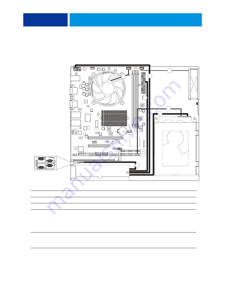
Checking connections
The most common cause of a hardware problem is a faulty or loose connection. Before you
replace a component, check all external connections, and then check all internal connections.
F
IGURE
9:
Cable diagram
Cable key
From
To
1. CPU fan cable
CPU fan
CPUFAN connector on the motherboard
2. Enclosed fan cable
Enclosed fan
FAN2 connector on the motherboard
3. HDD data cable
HDD data connector
SATA1 on the motherboard
4. Power supply cables
Power supply
a. SATA power connector—HDD
b. 8-pin motherboard connector (pins 1–4 are used)
c. 24-pin motherboard connector (pins 1–20 are used)
d. Black and white leads on power switch
5. Power button cables
Power button
a. SW cable—J14 (pins 6 and 8)
b. SW LED cable—J14 (pins 2 and 4)
(For details, see
HDD
4a
5
2
CPU
fan
Power supply
Enclosed fan
4b
4c
3
1
4d
Connect one wire to A
and the other wire to B.
Power switch detail,
inside view
A
B


