Reproduction forbidden without Fibocom Wireless Inc. written authorization - All Rights Reserved
FIBOCOM L610-LA Series Hardware Guide
Page 39 of
49
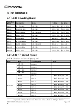
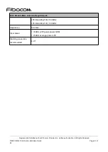
Mode
Band
Tx Power(dBm)
Note
Band 66
23+1/-3
10MHz Bandwidth, 1 RB
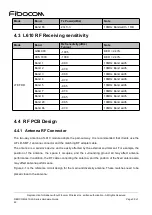
4.3 L610 RF Receiving sensitivity
Mode
Band
Rx Sensitivity(dBm)
Typical
Note
GSM 900
-109.5
BER < 2.43%
DCS 1800
-108.0
BER < 2.43%
LTE FDD
Band 1
-98.0
10MHz Band width
Band 2
-97.0
10MHz Band width
Band 3
-98.0
10MHz Band width
Band 4
-97.0
10MHz Band width
Band 5
-98.5
10MHz Band width
Band 7
-97.0
10MHz Band width
Band 8
-98.5
10MHz Band width
Band 28
-98.5
10MHz Band width
Band 66
-97.0
10MHz Band width
4.4 RF PCB Design
4.4.1 Antenna RF Connector
The two-way antenna of L610 module adopts the pad-out way. It is recommended that clients use the
U.FL-R-SMT-1 antenna connector and the matching RF adapter cable.
The antenna is a sensitive device and is easily affected by the external environment. For example, the
position of the antenna, the space it occupies, and the surrounding ground all may affect antenna
performance. In addition, the RF cable connecting the antenna, and the position of the fixed antenna also
may affect antenna performance.
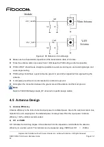
Figure 4-1 is the reference circuit design for the main and diversity antenna. These matches need to be
placed close to the antenna:


