L831-EA Module Hardware User Manual
Page 28 of 43
5.3 Index Signal
5.3.1 Index Signal Pins
L831-EA module used for providing drain output signal and indicate RF condition:
Pin #
Name
Description
10
LED1#
Close or open the condition indication of RF network, CMOS 3.3V
The condition description of LED1# signal as listed below :
No.
Condition
LED1#
1
RF open
Low level
2
RF closed
High level
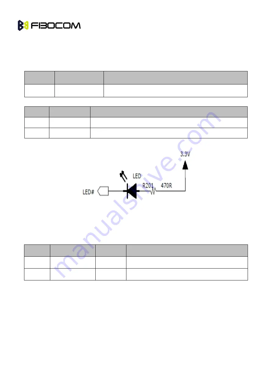
The recommended design as follows:
Figure5- 5 Recommended design of LED condition index
5.4 USB Interface
5.4.1 Definition of USB Interface
Pin No
Pin Name
I/O
Description
7
USB_DP
I/O
USB
8
USB_DM
I/O
USB signal-
L831-EA wireless module supports USB 2.0. It should be installed USB driver before using on PC.
While L831-EA wireless module plugged into the PC, the USB interface with the drive can map 3 COM
ports and 4 NCM ports at PC end of Windows system, and for details as listed below:
Two COM ports for sending AT Commands.
One COM port for tracing LOG information.
Four NCM ports are VLAN ports, mainly used for initiating data services .
Note: The COM port can used as Modem COM port and initiate data services. But cause of the speed of


