3 Application Interface
Copyright © Fibocom Wireless Inc.
43
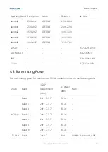
Pin Pin Name
I/O Reset Value Pin Description
Level
58
RFFE_SDATA
I/O PD
Tunable ANT control, MIPI Interface,
RFFE data
1.8V
59
ANTCTL0
O PD
Tunable ANT CTRL0, default low
1.8V
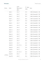
61
ANTCTL1
O PD
Tunable ANT CTRL1, default low
1.8V
63
ANTCTL2
O PD
Tunable ANT CTRL2, default low
1.8V
65
ANTCTL3
O PD
Tunable ANT CTRL3, default low
1.8V
3.9
Configuration Interface
The FM101 module provides 4 configuration pins, they are output pins, used to read the
level of H/L for the host system, so the host system can know the module type insert in
the M.2 slot. If the host system is not need to know the module type, that is no need to
connect these 4 pins, let they are floating is OK.
This module is configured as the WWAN-SSIC-0 type M.2 module:
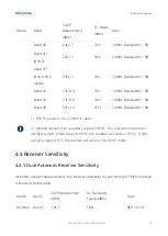
Pin Pin Name I/O Reset Value Pin Description
Type
1
CONFIG_3 O
GND
GND, FM101 M.2 module is
configured as the WWAN – SSIC,
USB 3.0 interface type
-
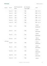
21
CONFIG_0 -
NC
NC, FM101 M.2 module is
configured as the WWAN – SSIC,
USB 3.0 interface type
-
69
CONFIG_1 O
GND
GND, FM101 M.2 module is
configured as the WWAN – SSIC,
USB 3.0 interface type
-
75
CONFIG_2 O
GND
GND, FM101 M.2 module is
configured as the WWAN – SSIC,
-


