Fiber Options S711D, Instruction Manual
The Fiber Options S711D Instruction Manual is available for free download on our website. This comprehensive manual provides detailed instructions on how to operate and maintain your product effectively. Don't miss out on this essential resource, download it now from manualshive.com for a seamless user experience.
Share
Download


Reviews:
No comments
Related manuals for S711D
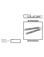
B1000
Brand: C-ducer Pages: 4

Artist T88
Brand: Audiocenter Pages: 40

C414EB
Brand: AKG Pages: 7

TTM-30
Brand: soundsation Pages: 16

T.Bone TWS ONE VOCAL
Brand: thomann Pages: 4

HCV 1035 BT
Brand: Trevi Pages: 46

C 8890B
Brand: Redback Pages: 16

Sound Pad S1
Brand: Hengbida Electronic Technology Pages: 19

MC-229I
Brand: Technika Pages: 16

CA-UXG1
Brand: JVC Pages: 51

CA-D301T
Brand: JVC Pages: 37
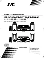
CA-FSSD550
Brand: JVC Pages: 27

CA-UXG110
Brand: JVC Pages: 24

CA-UXF2B
Brand: JVC Pages: 2

CA-UXF70MD
Brand: JVC Pages: 72

CA-UXF3B
Brand: JVC Pages: 58

CA-MXJ70
Brand: JVC Pages: 34

AX-UXTB3
Brand: JVC Pages: 28


