background image

15

ADvAnCED PARAMETERS

#10: Advanced parameters

The Wall Plug allows to customize its operation to user’s needs. The 

settings are available in the FIBARO interface as simple options that 

may be chosen by selecting the appropriate box.
In order to configure the Wall Plug (using the FIBARO home Center 

controller):
1.  Go to the device options by clicking the icon:   
2.  Select the „Advanced” tab.
3.  Modify values of chosen parameters.
4.  Save the changes.

GENERAL SETTINGS
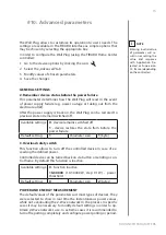
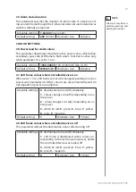
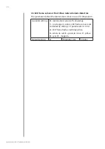
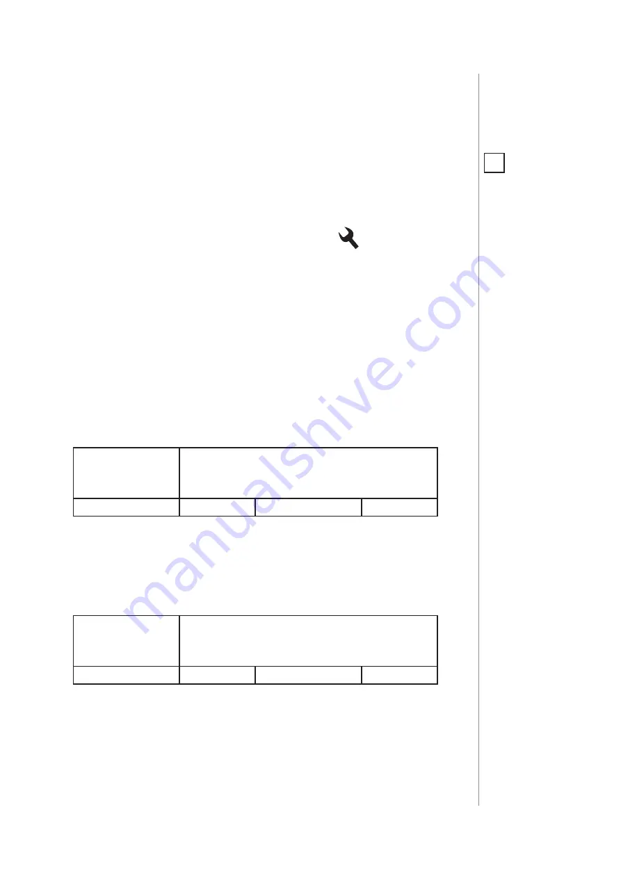
2. Remember device status before the power failure

This parameter determines how the Wall Plug will react in the event 

of power supply failure (e.g. power outage or taking out from the 

electrical outlet). 
After the power supply is back on, the Wall Plug can be restored to 

previous state or remain switched off. 

Available settings:

0

 - device remains switched off

1

 - device restores the state from before the 

power failure

Default setting: 

1

Parameter size:

1

 [byte]

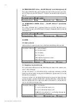
3. Overload safety switch

This function allows to turn off the controlled device in case of ex-

ceeding the defined power. 
Controlled device can be turned back on via button or sending a con-

trol frame. By default this function is inactive. 

Available settings:

0

 - function inactive

10-30000

 (1.0-3000.0W, step 0.1W) - power  

threshold

Default setting: 

0

Parameter size:

2

 [bytes]

POWER AND ENERGY MEASUREMENT

The default values of the parameters suit most types of devices. They 

were selected to show in real time the instantaneous power values, 

while not overloading the Z-Wave network in the process. In specific 

cases it may be necessary to modify default settings in order to op-

timize Z-Wave network’s use. In extreme cases it is recommended to 

turn off reporting completely and configure power polling or period-

NOTE

Entering invalid value 

of parameter will re-

sult in not setting the 

value and response 

with Application Re-

jected or Supervision 

CC frame (depending 

on the controller). 

i

Summary of Contents for FGWPG-121

Page 1: ...g the device 6 5 Operating the device 7 6 Power and energy consumption 9 7 Association 10 8 Z Wave range test 11 9 Z Wave specification 12 10 Advanced parameters 15 11 Specifications 21 12 Regulations 22 FIBARO WALL PLUG Type G with USB charger FGWPG 121 O P E R A T I N G M A N U A L EN v1 0 ...

Page 2: ...art home automation system based on the Z Wave protocol All of available devices can be controlled through a computer PC or Mac smartphone or tablet Z Wave devices are not only receivers but can also repeat the signal increasing the Z Wave network s range It gives advantage over traditional wireless systems that require direct link between transmitter and receiver as a result the construction of t...

Page 3: ... multi colour LED frame FIBARO Wall Plug is a remotely controlled plug in switch with the ability to measure power and energy consumption It uses a LED frame to visualize the current load and operating mode with colour changing illumination Our smart plug makes it possible to control electrical devices in a convenient and maintenance free way It is also equipped with a USB charging port with power...

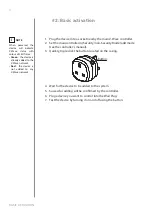
Page 4: ...cated on the casing 4 Wait for the device to be added to the system 5 Successful adding will be confirmed by the controller 6 Plug a device you want to control into the Wall Plug 7 Test the device by turning it on and off using the button NOTE When powered the device will indicate Z Wave status with colour of LED frame Green the device is already added to the Z Wave network Red the device is not a...

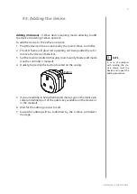
Page 5: ...otherwise 3 Set the main controller in Security non Security Mode add mode see the controller s manual 4 Quickly triple click the button located on the casing 5 If you are adding in S2 Authenticated mode type in the device pin code underlined part of the public key available on the device or in the manual 6 Wait for the adding process to end 7 Successful adding will be confirmed by the Z Wave cont...

Page 6: ...ame will glow green signalling being added removing is not necessary otherwise 3 Set the main controller into remove mode see the controller s manual 4 Quickly triple click the button located on the casing 5 Wait for the removing process to end 6 Successful removing will be confirmed by the Z Wave controller s message NOTE Removing theWall Plug from the Z Wave net work restores all the default par...

Page 7: ...ce plugged into a mains sock et the device signals it with blink green added red not added Range of the Z Wave network signalled with colour depending on type of communication or the lack of it only in range tester mode Menu position signalled with colour assigned to position Ongoing software update signalled with cyan blinking Hardware fault state error in communication with radio chip device sec...

Page 8: ...remov ing described in Add ing the device on page 5 i Controlling the Wall Plug with FIBARO Home Center controller The Wall Plug after successful adding is represented in the Home Center interface with two icons Device allows to turn on and off the device and displays current active power and cumulative en ergy consumption USB port icon displays current active power and cumulative energy consumpti...

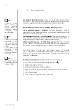
Page 9: ...power that energy receiver is changing into a work or a heat The unit of active power is Watt W Electric energy energy consumed by a device through a time period Consumers of electricity in households are billed by sup pliers on the basis of active power used in given unit of time Most commonly measured in kilowatt hour kWh One kilowatt hour is equal to one kilowatt of power consumed over period o...

Page 10: ...all Plug in 2nd and 3rd group allows to control up to 5 regular or multichannel devices per an association group LifeLine group is reserved solely for the controller and hence only 1 node can be assigned Association linking devices direct control of other devices within the Z Wave system network e g Dimmer Relay Switch Roller Shutter or scene may be controlled only through a Z Wave controller NOTE...

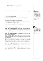
Page 11: ...pulsing yellow the Wall Plug tries to establish a routed communication with the main controller through other mod ules repeaters Visual indicator glowing yellow the Wall Plug communicates with the main controller through the other modules After 2 seconds the device will retry to establish a direct communication with the main controller which will be signalled with visual indicator pulsing green Vi...

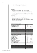
Page 12: ... 0x70 V1 YES CRC_16_ENCAP 0x56 V1 NOTIFICATION 0x71 V8 YES PROTECTION 0x75 V1 YES FIRMWARE_UPDATE_MD 0x7A V4 YES MULTI_CHANNEL 0x60 V4 YES BASIC 0x20 V1 YES 9 Z Wave specification Endpoint 1 Generic Device Class GENERIC_TYPE_SWITCH_BINARY Specific Device Class SPECIFIC_TYPE_POWER_SWITCH_BINARY Description represents the main B type socket allows to turn on off connected device and measure its acti...

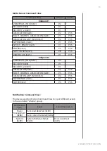
Page 13: ...d Class Version Secure Endpoint 1 ZWAVEPLUS_INFO 0x5E V2 SECURITY 0x98 V1 SECURITY_2 0x9F V1 ASSOCIATION 0x85 V2 YES MULTI_CHANNEL_ASSOCIATION 0x8E V3 YES ASSOCIATION_GRP_INFO 0x59 V2 YES SUPERVISION 0x6C V1 YES SWITCH_BINARY 0x25 V1 YES METER 0x32 V3 YES NOTIFICATION 0x71 V8 YES PROTECTION 0x75 V1 YES Endpoint 2 ZWAVEPLUS_INFO 0x5E V2 SECURITY 0x98 V1 SECURITY_2 0x9F V1 ASSOCIATION 0x85 V2 YES MU...

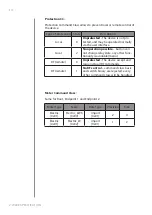
Page 14: ...on possible button can not change relay state any other func tionality is available menu RF remote 0 Unprotected The device accept and respond to all RF Commands RF remote 1 No RF control command class basic and switch binary are rejected every other command class will be handled Meter Command Class Same for Root Endpoint 1 and Endpoint 2 Meter Type Scale Rate Type Precision Size Electric 0x01 Ele...

Page 15: ...rom before the power failure Default setting 1 Parameter size 1 byte 3 Overload safety switch This function allows to turn off the controlled device in case of ex ceeding the defined power Controlled device can be turned back on via button or sending a con trol frame By default this function is inactive Available settings 0 function inactive 10 30000 1 0 3000 0W step 0 1W power threshold Default s...

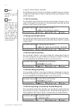
Page 16: ...orded or if chang es are insignificant By default reports are sent every hour Available settings 0 periodic reports inactive 30 32400 in seconds Default setting 3600 1h Parameter size 2 bytes 14 Periodic energy reporting This parameter defines time period between independent reports sent when changes in power load have not been recorded or if chang es are insignificant By default reports are sent ...

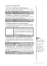
Page 17: ...h value set in parameter 26 only if power exceeded value of parameter 21 2 send frame with value set in parameter 27 only if power dropped below value of parame ter 22 3 send frame in both cases Default setting 3 Parameter size 1 byte 24 SWITCH ON value On Off Button association group 2 The value of BASIC SET command frame sent to the devices associat ed in 2nd group On Off Button when turning the...

Page 18: ... settings 1 general alarm 2 smoke alarm 4 CO alarm 8 CO2 alarm 16 high temperature alarm 32 flood alarm Default setting 63 all Parameter size 1 byte 31 Response to alarm frames This parameter defines how the Wall Plug will respond to alarms de vice s status change In case of values 1 or 2 the Wall Plug is operating normally and LED frame signals an alarm through time defined in parameter 32 or unt...

Page 19: ...n set to 1 or 2 LED frame colour will change depending on active power and parameter 40 Other colours are set permanently and do not depend on power consumption Available settings 0 illumination turned off completely 1 colour changes smoothly depending on ac tive power 2 colour changes in steps depending on ac tive power 3 white 4 red 5 green 6 blue 7 yellow 8 cyan 9 magenta Default setting 1 Para...

Page 20: ...mination colour in case of Z Wave alarm Available settings 0 illumination turned off completely 1 no change in colour LED frame colour is de termined by settings of parameters 41 or 42 2 LED frame flashes red blue white 3 white 4 red 5 green 6 blue 7 yellow 8 cyan 9 magenta Default setting 2 Parameter size 1 byte ...

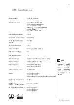
Page 21: ...scent loads 8A Inductive general purpose cosφ 0 75 0 8 13A Pilot duty cosφ 0 35 700VA Motor 750W Electronic ballasts 3A 2 5kV 80A 20ms BS 1363 Class I Micro gap relay switch μ 5V 1A 2 home and office use indoor only Z Wave 500 series chip 868 0 868 6 MHz EU 869 7 870 0 MHz EU 0 5dBm EU up to 50m outdoors up to 40m indoors depending on terrain and building structure 0 40 C 56 x 56 x 58 5mm RED 2014...

Page 22: ...nd product names referred to herein are trademarks of their respective holders Warning This product is not a toy Keep away from children and animals Declaration of conformity Hereby FibarGroupS A declaresthatthedeviceisincompli ance with Directives 2014 53 EU and 2011 65 EU 2015 863 The full text of the EU declaration of conformity is available at the following internet address www manuals fibaro ...

Reviews: