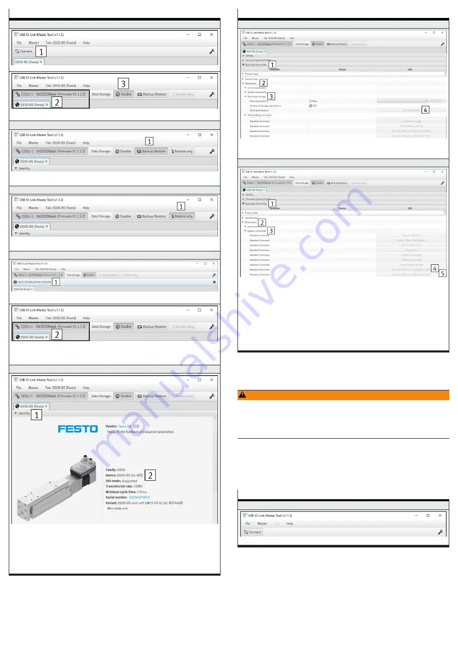
Steps for executing the data storage function
3. Establish a connection to the IO-Link Master
–
Press the "Connect
1
" button
–
The connection is established
2
–
Default setting: the data storage function is disabled — the "Disable
3
" button is active
4. Activate automatic saving (backup)
–
In the "Data Storage" tab press the "Backup/Restore
1
" button
–
The predefined application data is automatically saved in the IO-Link master with every change
5. Activate one-time storage (restore only)
–
In the "Data Storage" tab press the "Restore only
1
" button
–
The predefined application data are saved once in the IO-Link master
6. Replace device
–
Disconnect the electrical connections at the integrated drive
–
The connection to the IO-Link master is interrupted
1
–
Electrically connect the new integrated drive to the IO-Link Master
–
The connection to the IO-Link Master is automatically re-established
2
–
After a successful compatibility check of the device ID "0x0000.0A ... 0C, DeviceID1 ... ID3", the
application data are automatically transferred to the integrated drive
7. Check the current status of the application data
–
Open the "Identity
1
" tab
–
Check the current device ID in the "Device
2
" parameter. The device ID must correspond to the
drive system in use
–
0x000259 (601): ELGS-TB
–
0x00025A (602): ELGS-BS
–
0x00025B (603): EGSS-BS
–
0x00025C (604): ELGE-TB
–
0x00025E (606): EPCS-BS
Steps for executing the data storage function
8. Save application data
–
Open the "Specialist (user role)
1
" tab
–
Open "Parameter
2
" and "Save parameter
3
" submenus
–
In the "Save parameters" parameter press the "Save parameter
4
" button
9. Reference the new drive system
–
Open the "Specialist (user role)
1
" tab
–
Open the "Parameter
2
" and "System commands
3
" submenus
–
Execute the default command ""Reference" movement"
4
Press one of the two following buttons for the default commands:
–
Execute "Reference" movement (False)
4
(= factory setting)
–
Execute "Reference" movement (True)
5
–
Note:
After successful homing with end position determination, the transmitted values of the param-
eters "0x0105.0, Position Start Press", "0x0106.0, End Position Out" and "0x0108.0, Inter-
mediate Position" are only retained if they are in the value range of the parameter "0x0106.0,
End position Out "of the new drive system. If exceeded, the transferred values are replaced by
the newly determined value of the parameter "0x0106.0, end position Out".
1) The use of the function depends on the application software.
Tab. 7: Steps for executing the data storage function
10.2
Parameter set
Updating parameter set
WARNING
Risk of Injury due to Unexpected Movement of Components
For vertical or slanted mounting position: when power is off, moving parts can
travel or fall uncontrolled into the lower end position.
• Bring moving parts of the product into a safe end position or secure them
against falling.
The integrated drive supports the update of the parameter set after a device
replacement. The parameter set contains the factory settings of the drive system.
Drive system-dependent parameters, such as maximum payload of the mecha-
nism, are determined at the first homing and stored.
The table shows all steps for updating the parameter set using the application
software of the Festo USB IO-Link Master CDSU-1 as an example.
Steps for updating the parameter set
1. Start the application software
–
Run app


