


Translation of the original instructions
© 2020 all rights reserved to Festo SE & Co. KG
1
About this document
1.1
Applicable Documents
All available documents for the product
è
2
Safety
2.1
Safety Instructions
–
Take into consideration the ambient conditions at the location of use.
–
Only use the product in original status without unauthorised modifications.
–
Observe labelling on the product.
–
Store the product in a cool, dry, UV-protected and corrosion-protected envir-
onment. Ensure that storage times are kept to a minimum.
–
Prior to mounting, installation and maintenance work: Switch off compressed
air supply and secure it from being switched back on.
–
Observe tightening torques. Unless otherwise specified, the tolerance is
± 20 %.
2.2
Intended Use
The intended use of the gripper kit for robots is for integration into the UR soft-
ware and hardware connection for handling tasks of payloads.
Use the product only as follows:
–
In perfect technical condition
–
Within the limits of the product defined by the technical data
–
In the industrial sector, in research laboratories, in assembly areas, in series
and special machines
–
Permanently mounted
2.3
Training of Qualified Personnel
Installation, commissioning, maintenance and disassembly should only be con-
ducted by qualified personnel.
The specialized personnel must be familiar with the installation and operation of
electrical and pneumatic control systems.
3
Service
Contact your regional Festo contact person if you have technical questions
è
4
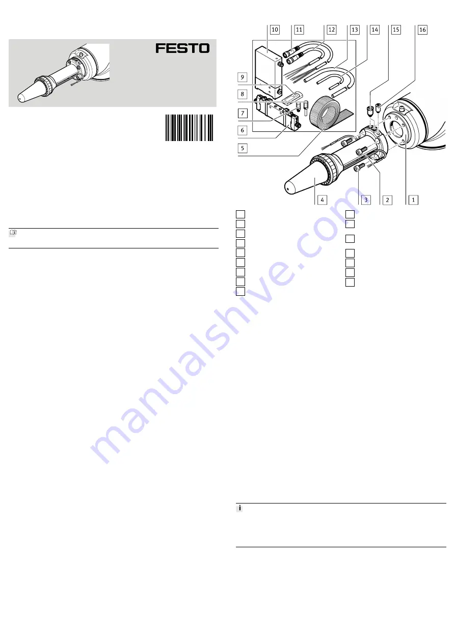
Design
1 Robot flange
2 Proximity sensor (2x)
3 Socket head screw (4x)
4 Adaptive shape gripper
5 Velcro strap (2 m)
6 Solenoid valve
7 Silencer UC-M5
8 Silencer UC-QS-4H
9 USB memory stick
10 Proportional-pressure regulator
11 Connecting cable NEBU-
M8G4-R-5-LE4
12 Connecting cable NEBU-
M8G3-R-5-LE3 (2x)
13 Tubing PUN-6 (4m)
14 Tubing PUN-4 (2m)
15 Push-in fitting QSM-M5-6-I (5x)
16 Push-in fitting QSM-M5-4-I
Fig. 1 Parts overview
4.1
Functional Principle
"Grip" /"Release"- only adaptive shape gripper active
The "Grip" /"Release" functions are intended for operation of the adaptive shape
gripper - without movement of the robot arm.
–
"Grip": the lower cylinder chamber is pressurised. The piston rod retracts.
–
"Release": the upper cylinder chamber is pressurised while the lower one is
exhausted. The piston rod advances. Then both chambers are exhausted
(neutral position).
"SmartGrip" - Adaptive shape gripper and robot arm active
The process "SmartGrip" consists of four phases:
1. The robot arm moves in the Z-direction by the "Workpiece distance" value.
2. The workpiece is detected and the proximity sensor switches.
3. After detection of the workpiece, the robot arm moves the adaptive shape
gripper further in the Z-direction towards the workpiece. The piston rod
moves into the adaptive shape gripper and the cap slides around the work-
piece. The distance travelled by the piston rod is determined by the "Work-
piece grip height" parameter.
4. If it returned over the defined path "Workpiece grip height", the lower piston
chamber is pressurised and the piston rod is fully retracted. The adaptive
shape gripper does not move further down during the active retracting pro-
cess.
"SmartRelease" - Adaptive suction gripper and robot arm active
When the workpiece is released, the gripper moves upwards in the Z-direction
over the full stroke (66 mm). At the same time, a pressure pulse is applied to the
upper piston chamber to advance the piston rod and release the object.
Precise placement
For precise placement, the gripped object should be positioned approx. 1 mm
above the support surface. If the object is completely enclosed by the cap, the
lower edge of the cap should be positioned accordingly.
5
Mechanical assembly
1. Screw push-in fittings
(2x) into ports A and B on the adaptive shape grip-
per.
aF
into port C on the adaptive shape gripper.
3. Position adaptive shape gripper
and tighten with
socket head screws
(4x). Tightening torque: 8 Nm
4. Screw push-in fittings
(3x) into ports 1, 2 and 4 on the solenoid valve
.
Tightening torque: 1.3 Nm
5. Screw silencer
(2x) into ports 3 and 5 on the solenoid valve
.
6. Plug silencer
into port 3 on the proportional-pressure regulator
aJ
.
8123229
DHEF-...-A-RA1
Adaptive shape gripper
8123229
2020-01
[8123231]
Instructions | Assembly, Installation, Parameterisation
Festo SE & Co. KG
Ruiter Straße 82
73734 Esslingen
Germany
+49 711 347-0
www.festo.com