
27 / 48
Festo 7DGE_25-63_ZR_KFb_en
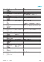
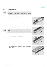
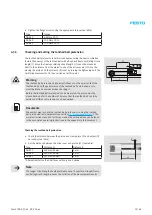
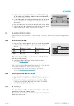
Cutting the new toothed belt to length
The exact length of the toothed belt in mm is the product of a basic length (L
0
) for the relevant type and the stroke of the
toothed belt axis, multiplied by a factor (F).
The stroke can be determined from the type codes on the name plate. Check the length of the new toothed belt and
shorten it if necessary to the length specified in the table (F × (L
0
+ stroke), see order example:
Type
Length L
0
Factor F
DGE-25
314 mm
1.989
DGE-25-…-GK
1)
314 mm
1.989
DGE-25-…-GV
2)
414 mm
1.989
DGE-25-…-HD
3)
25
332 mm
1.989
DGE-25-…-HD
3)
40
378 mm
1.989
DGE-40
489 mm
1.998
DGE-40-…-GK
1)
489 mm
1.998
DGE-40-…-GV
2)
659 mm
1.998
DGE-40-…-HD
3)
40
398 mm
1.998
DGE-63
785 mm
1.996
DGE-63-…-GK
1)
785 mm
1.996
DGE-63-…-GV
2)
1,035 mm
1.996
1)
GK: Standard slide
2)
GV: Extended slide
3)
HD: Heavy-duty version
Example: DGE-25-500-ZR-…-GK
Length L
0
:
314 mm
Stroke:
500 mm
Factor F:
1.989
Toothed belt length = F × (L
0
+ stroke) = 1,619 mm
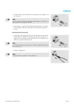
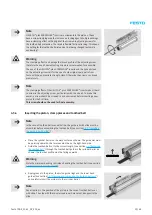
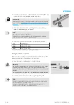
Note
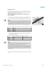
Sturdy general purpose scissors or metal shears are best for cutting the toothed belt.
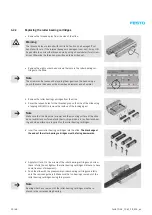
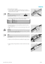
Warning
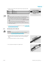
Do not bend or fold the toothed belt, as this can result in damage to the tensile bodies and shorten its service life by
tearing it. Note the minimum bending radius for assembly and storage:
DGE-25: R
min
= 6 mm
DGE-40: R
min
= 10 mm
DGE-63: R
min
= 20 mm
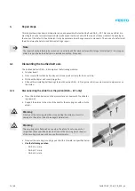
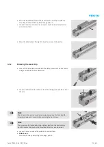
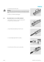
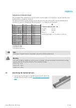
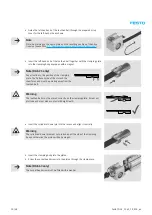
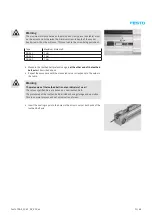
4.5
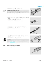
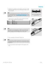
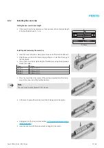
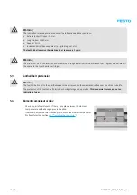
Assembling the toothed belt axis
• If you have not already done so, assemble the guide rail with slide on the
cylinder barrel as described in section
Summary of Contents for DGE-25 ZR RF Series
Page 47: ......
Page 48: ......
Page 49: ...Operating instructions en Toothed belt pretension test equipment 7Tension01_TBb_en...


