


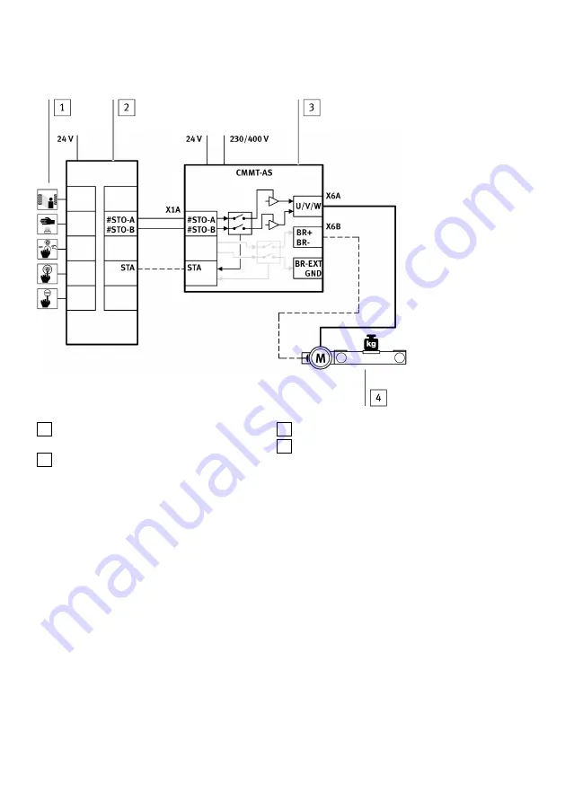
1 Input device for safety request (e.g. light cur-
tain)
2 Safety relay unit
3 Servo drive CMMT-AS
4 Drive axle
Fig. 13 STO sample circuit
Information on the sample circuit
The safety request is passed on to the servo drive on 2 channels via the inputs #STO-A and #STO-B at
the connection [X1A]. This safety request results in the 2-channel switch-off of the driver supply to the
servo drive's power output stage. The safety relay unit can use the STA diagnostic output to monitor
whether the safe status has been reached for the safety sub-function STO.
5.3
SBC installation
Inputs and outputs for the safety sub-function SBC
The 2-channel request for the safety sub-function is made via the digital inputs #SBC-A and #SBC-B at
the connection [X1A]. The SBA diagnostic output indicates whether the safe status has been reached
for the safety sub-function SBC. The holding brake is connected via the connection [X6B]. The external
clamping unit is connected via the connection [X1C].
Installation
24
Festo — CMMT-AS-...-S1 — 2018-10a
Summary of Contents for CMTT-AS S1 Series
Page 45: ......